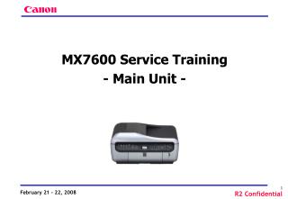
MX7600 Service Training - Main Unit -
MX7600 Service Training - Main Unit -. 1. PgR Technology 2. Special Notes on Servicing 3. FAQ 4. Other. 1. PgR (Pigment Reaction) Technology.

MX7600 Service Training - Main Unit -
E N D
Presentation Transcript
MX7600 Service Training - Main Unit -
1. PgR Technology 2. Special Notes on Servicing 3. FAQ 4. Other
1. PgR (Pigment Reaction) Technology A new ink system for printing on plain paper; Clear ink is applied over the entire surface of the print side of paper first, then pigment-based ink is ejected on it. Suitable for business use, with high photo-quality printing and high weather resistance and high waterproof, all on plain paper
Paper Paper Clear ink • Clear ink composition • Nitrate included • How Clear ink works • Agglutinates pigments on the paper surface. • => Realizes high brightness and high density of printing. • How Clear ink is applied to the paper • Prior to printing, Clear ink is applied thinly and evenly over the entire surface of the paper. • Effects • Anti-bleeding (no blurred printing), high brightness Ink fixes on the paper surface, and does not pass through the paper. Ink passes through paper. Pigment ink only Clear ink + Pigment ink
Advantages of Clear ink and pigment ink Disadvantages of use of pigment link alone Advantages of use of pigment ink alone ● Water resistance (color & black) ● Resistance to ink smudges due to highlighter pen ● Weather resistance X Feathering due to insufficient density X Bleeding X Paper curling over time after printing + MX7600 When Clear ink is used with pigment ink • ● Same print quality on any types of paper • High quality printing on recycled paper, etc. • ● High brightness (color & black) • High OD value • ● High sharpness (color & black) • Less feathering • ● Anti-bleeding • No bleeding on the color boundaries • ● Anti-curling • Curling prevention by anti-curling agent • ● Print-through prevention • Low possibility of print-through, which is effective especially in printing on both sides of paper
PgR TechnologyApplicable Paper Types and Paper Feeding Method The PgR technology is applied only to the plain paper, and not applied to the other papers, such as photo paper and postcard. Plain paper is to feed from the cassette, while photo paper and postcard are to feed from the rear tray. No PgR technology Rear tray • Photo paper • Postcard PgR Technology Cassette • Plain paper
Paper feed path length (RCT roller, PF roller, LF roller) > A4 paper length PF roller (1 location) Counter roller Paper feed from the cassette RCT roller RCT cap Clear ink coating Plain paper LF roller Pick-up roller • Mechanical restrictions on Clear ink application • Clear ink is applied to the paper by the transfer roller. If the roller stops in mid-operation, Clear ink is not applied evenly. • Clear ink application must be completed without any intermission (prior to the start of printing). • => Longer paper feed path from the cassette than the other • middle range models. • Note: Only with LGL paper, the Clear ink application stops and resumes at the bottom of the paper as per the specifications (to keep the printer body size).
Printer unit layout Sheet feeder unit (including Clear ink coating mechanism) Purge unit with pigment ink wiping using wetting liquid Valve unit, supplying Clear ink RCT main tank
Counter roller Paper Clear ink RCT roller RCT cap Clear ink Clear ink • Clear ink coating mechanism • Press the RCT cap against the RCT roller. • With negative pressure inside the RCT cap, fill the cap with Clear ink and circulate it. • Rotate the RCT roller to make the thin Clear ink film over the roller surface. • Pass the paper between the counter roller and the RCT roller, while transferring the Clear ink to the paper surface.
Clear ink coating mechanism • Clear ink supply and circulation flow • Components • Main tank • Buffer tank • High-level sensor • Low-level sensor • Pump (tube pump) • Valve x 5 • Liquid sensor • Basic operation • Supply from the main tank to the buffer tank • Supply from the buffer tank to the RCT cap, and circulation • Return from the RCT cap to the buffer tank • Standby
Clear ink coating mechanism • Supply from the main tank to the buffer tank • Status • Valve A: Close • Valve B: Close • Valve C: Close • Valve D: Open • Valve E: Open • Air through the main tank • Air through the buffer tank • Operation • Close the circulation flow, and pump the Clear ink from the main tank to the buffer tank. • The high-level sensor controls when to stop the Clear ink supply. Close Close Open Close Open
Clear ink coating mechanism • Supply to the RTC cap and circulation (during application of Clear ink to the entire paper surface) • Status • Valve A: Close • Valve B: Open • Valve C: Open • Valve D: Close • Valve E: Close • Main tank closed • Air through the buffer tank • Operation • Close the circulation flow, and pump the Clear ink from the buffer tank through the cap to the buffer tank again. Close Open Close Open Close
Clear ink coating mechanism • Returning from the RCT cap (after the end of printing) • Status • Valve A: Open • Valve B: Close • Valve C: Open • Valve D: Close • Valve E: Close • Main tank closed • Air through the buffer tank • Operation • Open the circulation flow, and pump to return the Clear ink from the RTC cap to the buffer tank. Open Close Close Open Close
Clear ink coating mechanism • Standby • Status • Valve A: Close • Valve B: Close • Valve C: Close • Valve D: Close • Valve E: Close • Main tank closed • Air through the buffer tank • Operation • The buffer tank has an open air-through hole, however, the hole is placed as far from the tank as possible, to prevent evaporation of Clear ink as much as possible. Close Close Close Close Close
Clear ink coating mechanism • Unit configuration: Consists of 3 portions • Each unit is connected by tubes. Valve unit (Valves A to E) Valve control & pump driving mechanism RCT main tank RCT cap RCT pump (Tube pump) Buffer tank
Matte Bk 0.85” 512 nozzles (600 dpi) Color 0.43” 512 nozzles (1200 dpi) (5-pl 256 nozzles, 2-pl 256 nozzles) (Tank side view) • Print head • ZF777 • (new for the MX7600 only) Nozzle layout Matte black: 256 nozzles, 300 dpi, 2 rows (zigzag alignment) Color (C / M): 5 pl, 256 nozzles, 600 dpi, bi-directional 2 pl, 256 nozzles, 600 dpi, bi-directional Color (Y / PBK): 5 pl, 256 nozzles, 600 dpi, 2 rows (zigzag alignment)
2. Special Notes on Servicing • 2-1. Service Test Print • Set paper in the cassette (no service test print from the rear tray). • Be sure to perform the service test print at every repair servicing. • To perform the Clear ink supply operation and examine whether the sensors inside the valve unit operate properly. • If either of the sensors is faulty, the service test print is not performed (no error indication). • When the service test print is not performed, “no clear ink” or “faulty sensor inside the valve unit” is suspected. Replace the clear ink tank or the valve unit. Supplemental information: If the machine continues to be used with a faulty sensor in the valve unit, excessive clear ink can be supplied, causing leakage of the clear ink. When both of the sensors detect presence of the clear ink, the service test print is performed, then the clear ink information of the EEPROM is automatically initialized after the service test print.
2-2. Paper Feed Roller Cleaning (Customer Maintenance) • When to perform: • When “The transport unit may not be clean.” is displayed. • (The message will be displayed at every 5,000 pages of printing, but timing is not disclosed to users.) • <LCD Message> • The transport unit may notbe clean.Perform sheet cleaning. • <See manual> • Tools required: • Cleaning Sheet (5 sheets packed with the machine) • Cleaning sheet availability (when missing, or used up): • To be supplied as a service part (QC2-6238)
2-3. Emptying the Buffer Tank • Background: • In repair servicing, the Clear ink may remain in the buffer tank during transportation of the printer between a user and a repair facility. • -> There may be a concern that Clear ink may leak during transportation (especially when returning the repaired unit from the repair facility to the user). • Conclusion: • No need to empty the buffer tank in servicing. • Reasons: • 1) No problems in the drop and vibration test without emptying the buffer tank. • 2) To empty the buffer tank, the special tools (tool tank, syringe, valve pressing tool) are required. • 3) There is a possibility of overlooking the procedures for disposing of the waste liquid (from the buffer tank) at a repair facility. • For refurbishment operation (USA only at the moment), however, we will consider setting the special tools.
2-4. Notes on Disassembly and Reassembly • Items required • Phillips screwdriver: 2 long screwdrivers • (1 for removal of screws, the other to be used • as a lever when removing the middle frame) • 1 short screwdriver (for removal of screws) • Flat-blade screwdriver: 1 (for removal of screws) • Tweezers: 1 (for handling the harnesses)
2-4-1. Power supply unit removal Previous models: The power supply unit can be replaced without removing the external housing. MX7600: The side cover L and 2 screws need to be removed. Be cautious of the harness. 2 screws to be removed
2-4-2. Separation of the printer unit from the bottom case Be cautious not to damage the tubes (by the screwdriver, etc.) between the valve unit and the sheet feeder unit. • 2-4-3. Printer unit assembly Be cautious not to bend or disconnect the tubes. • 2-4-4. Tube connection If the tube is wet with Clear ink, it may be disconnected from the joint. Be sure to wipe off Clear ink from the tube before connecting it. Details to be explained in “Disassembly & Reassembly.”
2-5. Operation Confirmation without Scanner and ADF • Purpose: • Confirm the printer engine operation without functionality of the scanner and the ADF (special mode) • Procedures for using the special mode: • 1) Press and hold the ON/OFF button. While holding the ON/OFF button, connect the AC power cord. • 2) Still holding the ON/OFF button, press the Stop/Reset button 8 times. • 3) Release the ON/OFF button. • Usage of the mode: • a. Confirm the printer engine operation. • (When an error occurs in the scanner or the ADF, the operation of the printer engine alone can be examined.) • b. Identify the faulty part between the printer engine and the scanner / ADF. • Supplemental information: • Same as power-on in the user mode. • Service mode functions not available. • Printing from a PC available. • No copy or scan operation.
3. FAQ To be given in the Technical Reference.
4. Guideline on Use of “Duty Cycle” • How to describe the specifications: • English: “Duty Cycle” • Product life: • Specified “print volume” or “year of use” whichever comes first. • Note: This is currently mentioned in the “Service Plan” issued by IJQA Center, and has been disclosed to the service section of each sales company (confidential information) • Definition: • “Duty Cycle” is the reference figures of the maximum print pages that the printer can print within a month. • Note: This numerical value represents the “maximum number” of printing pages, while it does not refer that the printer can print such figures, constantly each and every month. • This numerical value varies based on printing method, printing contents, and the papers.
4. Guideline on Use of “Duty Cycle” • When a customer requires the basis of the “Duty cycle” figures: • The evaluation method which leads to the figures cannot be disclosed at any cases. • (Exception) • When the requirement is essential to the business (e.g. spot deal from the major account, etc.), information disclosure should be determined by both sales companies and CINC IJQA Center, as it is now. • Effective time / model / specifications: • Effective from: 2008 1Q • Model: MX7600 • Specifications: Duty cycle up to 7,500 pages per month