Download
1 / 59
2.48k likes | 5.81k Views
Bergamo University Italy 12 th -14 th June 2012. Lecture 1- Introduction to Vehicle Dynamics. Professor Mike Blundell Phd , MSc, BSc ( Hons ), FIMechE , CEng. Contents. Vehicle Dynamics Background Multi-Body Dynamics Background Applications with Multi-Body Systems Analysis.

E N D
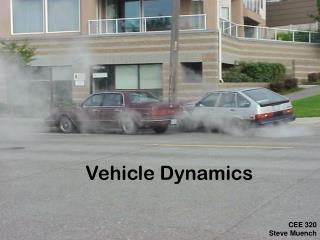
Bergamo University Italy 12th-14th June 2012 Lecture 1- Introduction to Vehicle Dynamics Professor Mike Blundell Phd, MSc, BSc (Hons), FIMechE, CEng
Contents • Vehicle Dynamics Background • Multi-Body Dynamics Background • Applications with Multi-Body Systems Analysis
What is Vehicle Dynamics? • Vehicles • wheels • motion • self powered • Dynamics • Greek “DYNAMIS” – power • ride • handling
First Recognised By? • Wheel invented in Mesopotamia 4000BC • Myceneans 1600-1200BC • Compliant Chariot Wheels • Willow or Elm Spokes
The Term “Suspension” • Horse Drawn Carriages (19th Century) • Leather Straps used to “suspend” the carriage
Some More Modern Developments • “Road manners of the modern motor car” (Olley, 1945) • “Theoretical prediction and experimental substantiation of the responses of the automobile to steering control” (Segel, 1956).
1960s Corvair • Ralph Nader • Rear Engine Corvair • Rear Suspension Problem • Rollover
Moose Avoidance Test • Consumer demand for tall vehicles impairs stability • City cars - narrow • Sports-utility – tall • MPV (minivan) - tall
Computer Power (1960s - Present) Apollo 11 computer 2.048 MHz CPU, Memory 74 kB, RAM 4kB Commercialisation of Finite Element Analysis NASTRAN (NASA STRUCTURAL ANALYSIS) Exponential Growth in Computer Processing Power and Computer Aided Engineering (CAE) Capability http://www.aprosys.com/img/06.pdf
Multibody Systems Analysis (MBS) Virtual Prototyping (MBS) may be summarised as: • The Analysis and Simulation of Mechanical Systems • Systems can consist of rigid and flexible bodies • Bodies are assembled using rigid joints or flexible connections • System elements such as springs and bushes can be nonlinear • The mechanism can move through large displacement motion • Automatic formation and solution of equations of motion • Animated and plotted presentation of results • Commercial Software available – ADAMS, SIMPACK, DADS, …
Applications in Industry Auto/Truck/Bus Rail/Off-road Aero/Defense General Machinery
Simulation of real-world systems Reduces time-intensive, costly, hardware build-test-refine cycles Improves quality Strategic industries: automotive, aerospace/defense, and rail Strategic Industries
The Simulation Process The Simulation Process may be summarised as: • IDEALISATION - Describe the real system by a 'model' containing rigid or flexible parts, joints, springs … • MODEL GENERATION - A pre-processor is used to generate a computer input file containing the data to describe the model … • GENERATE EQUATIONS - The equations of motion for the system are automatically formulated. • EQUATION SOLUTION - The equations of motion are assembled in matrix form and solved to provide outputs. • PRESENTATION OF RESULTS - On completion of the analysis a postprocessor is used to present results.
Basic Componentsof an ADAMS Model • PARTS - Rigid Bodies. Definition by mass, mass centre, and mass moments of inertia. Every model must include a fixed GROUND part. • MARKERS - Defined as a point fixed on a part. Belongs to and moves with the part during the simulation. Used to define the location and orientation of mass centres, joints, springs, bushes ... • JOINTS - A library of standard joints. A joint connects two parts. The relative motion is constrained by joint type. • MOTIONS - Used to input translational or rotational displacements. Can only be input at certain joints and are defined as a function of time. • FORCES - Can be linear or nonlinear and translational or rotational. Body forces and joint reactions are calculated automatically displacement motion.
Spherical Cylindrical Revolute Translational Planar Fixed Universal Rack & Pinion Typical Constraint Elements - Joints
Main Types of Analysis • KINEMATIC - Movement controlled by joint selection and motion inputs. Movements not effected by external forces or mass properties. Systems have zero rigid body Degrees of Freedom. • STATIC - Determine static equilibrium position and reaction forces. Velocities and accelerations are set to zero. Often needed before dynamic analysis (ie. full vehicle models). Can be run QUASI-STATIC in time domain. • DYNAMIC - Complete nonlinear transient multi-degree of freedom systems using numerical integration to solve the equations of motion. Users can select the integrator for solution and control the accuracy of the solution process.
Bump Bump Movement (mm) 100 I Time (s) 0.5 0.25 0.75 1.0 -100 Rebound INPLANE MOTION J Double WishboneWheel Travel Simulation
Centre Line A B Instant Centre Roll Centre Height D C Roll Centre z y Wheel Base (WB) Suspension Calculations • Camber Angle versus Bump Movement (Wheel Travel) • Caster Angle versus Bump Movement • Steer Angle (Toe) versus Bump Movement • Track Change versus Bump Movement • Roll Centre Location
30 m 25 m 25 m 30 m 15 m A C B ISO Lane Change Manoeuvre
Vehicle and Tyre Modelling • ADAMS Full Vehicle Model - 160 DOF • All linkages and nonlinear bushes modelled • Subframes and body torsional stiffness included • Roll bars modelled as Finite Element type beams • Compliance in the steering column included • Driveline, speed and steering controllers • Full Interpolation Tyre Model
Model Elaboration (Sharp) “Models do not possess intrinsic value. They are for solving problems. They should be thought of in relation to the problem or range of problems which they are intended to solve. The ideal model is that with minimum complexity which is capable of solving the problems of concern with an acceptable risk of the solution being “wrong”. This acceptable risk is not quantifiable and it must remain a matter of judgement. However, it is clear that diminishing returns are obtained for model elaboration.” Sharp, R.S. Computer codes for road vehicle dynamic models. Institution of Mechanical Engineers Paper 427/16/064, Autotech '91, Birmingham, November 1991.
The Myth of Accuracy (Harty) • There exists a commonly held, if rarely spoken, belief that the usefulness of any predictive model is directly related to its accuracy as measured against the real world. In a deliberately contentious manner, this belief is tested and found wanting with several examples of real world processes. There is a time when sufficient accuracy is optimum. • “The Paralysis of Analysis” • Three Possible Methodologies • One Complex model for all Problems • Several models optimised for the task in hand • Models with evolving complexity • “The siren voice of added complexity must be resisted as a habit” • Harty, D. The Myth of Accuracy, The Journal of the Engineering Integrity Society, January 1999.
LINKAGE MODEL LUMPED MASS MODEL SWING ARM MODEL ROLL STIFFNESS MODEL Full Vehicle Modelling Strategies
Tyre Modelling Simulation of Vehicle Handling • -Interpolation models (Lookup Tables) • -Simple Equation based representations (Fiala) • -Complex Mathematical Fits to Test Data (Magic Formula) • -Pure and Combined Slip Models • Prediction of Vehicle Ride Quality • -Simple Physical Models (Stiffness/Damping) • -More Advanced Physical Models (FTire) • Determination of Component Loading • -Simple Physical Models (Equivalent Volume) • -More Advanced Physical Models (FTire) • -Full Non-Linear Finite Element Models Complex Friction/Stress Behaviour in the Tyre Contact Patch
Tyre Testing • Lateral force with slip/camber angle • Aligning moment with slip/camber angle • Longitudinal force with slip ratio Fy Slip Angle Courtesy of Dunlop TYRES Ltd.
Tyre Model Fx Fy Tyre Model Mz Fx Fy Fz Mz Fz Vehicle/Tyre Model Interaction VEHICLE MODEL Wheel centre - Position, Orientation and Velocities Mathematical Solution at Integration Time Steps TYRE MODEL Fx - longitudinal tractive or braking force Fy - lateral cornering force Fz - vertical normal force Mz - aligning moment Mx - overturning moment My - rolling resistance moment
Fy Slip Angle a Virtual Rig Tyre Model and Data Assessment LPTM AIRCRAFT TYRE MODEL FIALA MODEL INTERPOLATION MODEL HARTY MODEL MAGIC FORMULA MODELS Check plots in ADAMS tyre rig model Aircraft Model Vehicle Model
Aircraft Tyre Modelling • EPSRC Project with AIRBUS UK • Simulate landing, takeoff, taxiing • Tyre Testing by Airbus in Toulouse • Developed model in a MATLAB/SIMULINK Environment with export to ADAMS • Low Parameter Model based on Harty Approach with extended Load/Speed dependence • Shimmy Modelling (Early NASA work) remains elusive
Vehicle Body or Sprung Mass z m Body Response Suspension Spring and Damper k c Zg Z Ground Input X Time (s) Ride Simulation (Comfort) Also important in Motorsport Vehicles Also important in Military Vehicles
Durability Computer Simulation of Proving Ground and Laboratory Test Processes
A Tyre Model for Ride & Durability Simulations A Flexible ring tyre model Tire phenomena based on a mechanical model The FTIRE Model Developed by Cosin (www.cosin.eu) FTire on Belgian Pave
Fy Lateral loads Fx Longitudinal loads Fz Vertical loads Component Load Prediction FINITE ELEMENT MODEL ADAMS MODEL
Typical Loadpaths 200 mm typical • Strut example • weight of car • cornering 600 mm typical 30 mm typical -20 - +30 mm typical 4000 N typical
Aircraft Dynamics • Modern Vehicle Dynamics evolved in the 1950s from Flight Dynamics • Segal (1956) describes work carried out on a Buick vehicle for General Motors based on transferable experience of aircraft stability gained at the Flight Research Department, Cornell Aeronautical Laboratory (CAL).
Aircraft Dynamics • Landing • Takeoff • Taxiing
Vehicle Products ADAMS/Car ADAMS/Chassis ADAMS/Tire