Download
1 / 40
400 likes | 424 Views
Discover the INtegrated Mapping FOr the sustainable development of Ireland’s MArine Resource (INFOMAR) program using LiDAR technology in coastal and offshore areas to collect crucial data for marine activities and research.

E N D
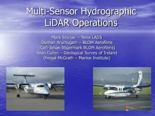
Multi-Sensor Hydrographic LiDAR Operations Mark Sinclair – Tenix LADS Dushan Arumugam – BLOM Aerofilms (Carl-Johan Stigermark BLOM Aerofilms) Sean Cullen – Geological Survey of Ireland (Fergal McGrath – Marine Institute)
INtegrated Mapping FOr the sustainable development of Ireland’s MArine Resource (INFOMAR) Program • Successor to Continental Shelf Delineation project 1995 – 1996 and Irish National Seabed Survey (INSS) 1999 – 2005 which mapped all Irish designated waters > 200 m deep and collected bathymetric, magnetic, gravity and ancillary datasets to support a range of activities and research • INSS also included ground truthing to acquire seabed samples, video transects and photographic evidence • In 2002, INSS included an initial trial airborne laser survey in Clew Bay
INFOMAR Program • INFOMAR program commenced in 2006 • priority to inshore areas • Joint management by Irish Marine Institute and Geological Survey of Ireland (GSI) • Program to collect, integrate and supply data to support a number of value added products and projects, including nautical charting, habitat mapping, infrastructure support and research • 20 year initiative, with first 10 years to map 26 priority bays and 3 offshore areas • In the initial 3 years a multi-platform mapping strategy has been adopted using vessels offshore and lidar in inshore areas and over the shoreline
INFOMAR 2008 LiDAR project • Areas surveyed included Donegal, N side Galway Bay, NW coast Aran Islands, Tralee Bay, Sligo Bays, Blacksod Bay and Lough Foyle • Nature of areas: • Donegal and Sligo bays, shallow and mostly intertidal • Galway bay, shallow sandy inter-tidal bay with moderate turbidity & west of Galway, steep-to rocky coastal area with kelp • Aran I and Blacksod Bay, sand and rock • Tralee Bay, sandy inter-tidal bay with extensive high ground close south • Lough Foyle, highly turbid bay on international border between Northern Ireland (UK) and Republic of Ireland
Strategy for LiDAR survey • Multi-sensor approach using 2 complementary LiDAR systems • In general, areas were allocated to each sensor as follows: • Hawk Eye 2 (BLOM Aerofilms) to survey shallow inter-tidal areas and small rocky bays • LADS Mk II (Tenix LADS) to survey larger coastal areas where the water was deeper and areas in vicinity of high ground. Shallow inter-tidal bays with turbidity were also surveyed.
General GSI Requirements • IHO order 1 position and depth accuracy • Depths to 20 meters (minimum of 10 meters) • 5x5 meters laser spot spacing • Caris readable data • Data to Malin Head datum in ASCII format (CZM) and to LAT datum in CARIS readable format (navigation / charting) • Data to ellipsoidal datum for checking new separation models • Seabed reflectivity data for interpretation of bottom-type
Hawk Eye – survey areas • Data capture in 3 areas • Donegal Bay • Sligo Bays • Greatmans & Cashla Bays (west of Galway) • Data captured from coastline down to the 10m contour
Hawk Eye – calibrations • Factory Calibrations • Laser alignment • Pixel range calibration • Absolute range calibration Hydro Laser Pixels Topo Laser Pixels
Hawk Eye – calibrations • Field Calibrations • Pitch, Roll and Heading • Absolute range in water and on land • Terramatch • Identify Heading, Roll and Pitch misalignments • Apply corrections to point cloud
Hawk Eye – verification • Sea Control Areas (SCA) • 2 SCAs at each area • Singlebeam echo-sounder survey • 30mx30m area • Ground Control Areas (GCA) • 2 GCAs at each area • PPK Survey • 10mx10m area
Hawk Eye – data processing • Applanix POSPac • Process trajectories • AHAB Coastal Survey Studio (CSS) • Bottom detection algorithm processing • Export point clouds to TerraScan cleaning software run on Microstation • TerraSolid (extension for MicroStation) • Data cleaning and output CARIS • Orthophoto production • CARIS • Creation of final data products
Hawk Eye – datums • Data was initially processed on the ellipsoid and then transformed to Malin Head datum and LAT • Ellipsoid to orthometric height using OSGM02 geoid model • Orthometric height to Malin head using a static offset at each bay (0.13m – 0.17m) • Orthometric height to LAT using a static offset at each bay (2.09m – 2.68m) • The static offsets were determined for each bay using tidal benchmarks and tide gauge data
LADS – survey areas • Data capture in 3 areas: • Galway Bay (N side) including Aran Islands • Tralee Bay – operations near high ground • Blacksod Bay • Data was captured from coastline down to the 10 - 20m contour (depending on water clarity in respective areas)
LADS – additional survey area • INFOMAR also engaged other stakeholders for a potential survey of Lough Foyle. • GSI, Marine Institute, Loughs Agency, Port of Londonderry, Environment NI and AFBI (Department of Agriculture) are relevant agencies • Lough Foyle is an environmentally sensitive marine habitat in a cross border region • Survey was extended to include this area • Turbidity management in this area was crucial
LADS – data collection • Data collected relative to the instantaneous mean sea surface • Data reduced to LAT and Malin Head datums through tide models using observed tides • Variable height capability important in managing low cloud and high ground, particularly on the south side of Tralee Bay • Flexibility to move between areas significantly separated
LADS – calibrations • Static and dynamic position checks and checks over known features were conducted • Benchmarks used for depth checking – common SCAs used in areas where both systems operated • Cross line comparisons • Analysis of overlapping data in common survey areas
LADS – operations • Operations based primarily on managing water clarity in the most turbid areas • When conditions unsuitable, diverted to alternative areas • Management of water clarity significantly impacted by flood / ebb and spring / neap tides • Wind strength and direction also significantly impacted selection of survey area • Cloud height and the vicinity of high terrain also had to be considered
LADS – survey life cycle including data processing • Data processing during field operations to keep up to date • Pre-validation to progressively appraise quality of data collected and identify where additional data is needed • Detailed validation and checking in depot following field operations • Approval of data by IHO cat A surveyor following quality control
LADS – coverage • Galway Bay and N coast
LADS – coverage • Aran Islands – west of Galway Bay
LADS – coverage • Tralee Bay
LADS – coverage • Blacksod Bay
LADS – coverage • Lough Foyle
Integration - datums • Typically Malin Head datum is determined at tide gauge sites. • LAT values are defined by software PolPred for each survey area relative to Malin Head datum • An important challenge for this survey has been the integration of data from an both an ellipsoidal datum (ETRF89 / GRS80)and geoidal datums (Malin Head / LAT) • This has been complicated by weaknesses in geoid / ellipsoid separation models in the survey areas on the west coast of Ireland • New software provides a model for this (VORF), but it has not been extensively verified
Integration – datums / formats • Malin Head datum in ASCII format • LAT datum in Caris readable format • Ellipsoidal datum – customer requested fields for ETRF89 / GRS80to be added to ASCII format records • Hawk Eye 2 ASCII Data Format • One file for each survey run • One record per sounding • Space separated fields for: • Latitude • Longitude • Depth • Easting • Northing
Integration - formats • LADS in CARIS Export Format (CAF), readable by CARIS and Fledermaus: One ASCII file for each area containing: • Survey summary data • Area Bounds • Spheroid • UTM zone etc • For each sounding • Sounding ID (run, frame, scan, sounding numbers) • Latitude • Longitude • Depth • Easting • Northing • Possible contending depth and positions
Integration - formats • ASPRS (The American Society for Photogrammetry and Remote Sensing) LAS Version 1.1 One binary file for each line containing: • Public header block • System Information • Total number of records • Min / max values • Variable length records • Developer defined (Project Info etc) • Point data • XYZi • Return number • Number of returns • Scan information • Classification (e.g. Ground, Low / Medium / High Vegetation, Buildings, Water)
Integration - checks • Comparisons between datasets • Datasets available for each area: • Seabed and Ground Control Areas (SCAs & GCAs) • Hawk Eye 2 Lidar data • LADS MKII Lidar data • A “mean” 1m grid was created for all datasets • Artefacts excluded (eg cars over GCA) • Compared using CARIS Base Editor – Surface Difference functionality
Integration - datums • Integration is still in progress and results are preliminary only Example of Hawk Eye 2 data against SCAs and GCAs in Sligo Bay
Integrating data and products • Preliminary results from Greatmans / Cashla between LADS and SCAs and Hawk Eye 2 data
Integrating data and products • QC • Area based reviews of each survey area conducted on ASCII data for both systems • Emphasis on: • Datums • Excessive noise spread due to artefacts e.g. turbidity • Data coverage • Anomalous soundings (large depth difference with respect to surroundings) • Primary tool used was QCTools (LADS proprietary software)
Integrating data and products • QC (Cont) • Key functions: • Depth difference grids • Profiles • Tinned 3-D images • Tinned contours • 3-D Editor in Fledermaus and CARIS also used • Queries logged and forwarded to respective survey teams for comment / action
Integrating data and products • Combined image of vicinity of Greatmans / Cashla (Hawk Eye) and Galway / Aran Islands (LADS)