Download
1 / 4
40 likes | 202 Views
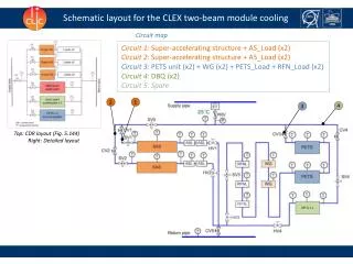
Schematic layout for the CLEX two-beam module cooling. Circuit map. Circuit 1: Super-accelerating structure + AS_Load (x2) Circuit 2: Super-accelerating structure + AS_Load (x2) Circuit 3: PETS unit (x2) + WG (x2) + PETS_Load + RFN_Load (x2 ) Circuit 4: DBQ (x2)

E N D
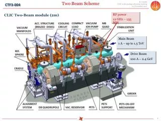
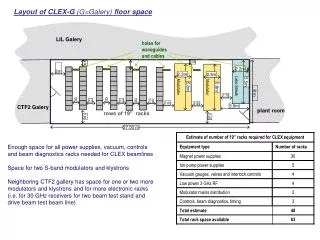
Schematic layout for the CLEX two-beam module cooling Circuit map Circuit 1: Super-accelerating structure + AS_Load(x2) Circuit 2: Super-accelerating structure + AS_Load (x2) Circuit 3: PETS unit (x2) + WG (x2) + PETS_Load + RFN_Load (x2) Circuit 4: DBQ (x2) Circuit 5: Spare 2 1 4 3 Top: CDR layout (Fig. 5.144) Right: Detailed layout
Cooling rack 3 1 4 2 1 3 2 4 Return pipe Isometric view Supply pipe Output Input
Cooling network of the Module Circuit 1 & 2: SAS & Loads Assembly Flowchart (link) The cooling network consists of copper pipes (OD 8, 10 and 16mm) and standard connectors (Swagelok) Circuit 3: PETS & Load, RFN & Load (Hybr.)
Open questions • Do we need the separate circuit for each DBQ? Now they are cooled in series. • What would be the material of pipes connecting the cooling rack and cooling network of the module? Plastic multilayer pipes, rigid copper pipes, Kevlar pipes. • The location of the cooling rack.