Numerical Methods in Electrical Engineering
610 likes | 788 Views
Join the workshop led by Professor David Thiel to learn about the Method of Moments and Finite-Difference Time-Domain for electromagnetic modelling. Discover the validation processes crucial for reliable solutions. Explore numerical EM techniques and procedures for solving fundamental electromagnetic geophysics problems. Gain insights on reducing prototypes through numerical modelling and verification techniques. Learn about the Modelling Process overview and the Method of Moments in this informative workshop.

Numerical Methods in Electrical Engineering
E N D
Presentation Transcript
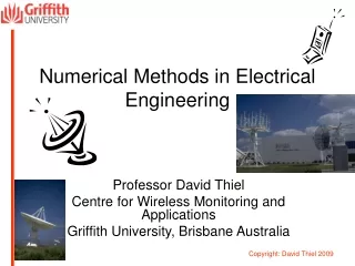
Numerical Methods in Electrical Engineering Professor David Thiel Centre for Wireless Monitoring and Applications Griffith University, Brisbane Australia
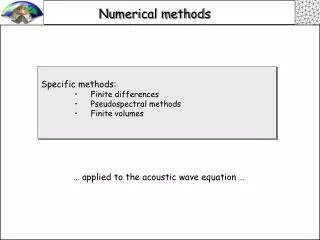
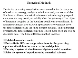
Purpose • This is a follow-on workshop from the Optimization workshop. • The aim is to introduce two methods of electromagnetic modelling: • The Method of Moments (MoM): frequency domain, open boundaries. • The Finite-Difference Time-Domain (FDTD): time domain, closed boundaries. • To outline the validation processes essential to obtaining reliable solutions.
My interest? • I wished to solve some fundamental problems in electromagnetic geophysics where subsurface targets were small and the earth was both highly conductive and semi-infinite. • I have worked with many numerical EM techniques including • MoM • FDTD • Impedance method • FEM • FDM • Spice (Circuit simulator)
Topics • Overview of Numerical Modelling for electromagnetics. • The Method of Moments. • The Finite-Difference Time-domain method. • Review.
Topic 1 Overview of the Modelling Process
Why numerical modelling? • To reduce the number of prototypes constructed. • To use as the forward solver in an optimization routine to gain the best possible design.
What are the alternatives? • Design and build lots of physical models • Time consuming • Expensive • Measurement difficulties (cables, calibration, mechanical precision, interference, mutual coupling, field confinement, etc) • Analytical solutions • Limited to simple models because of the computational complexity
But for Verification …. • You MUST make a physical model! • You MUST undertake some simple theoretical modelling for use in your numerical modelling analysis! • If you don’t, you have no verification of your model and the results are not acceptable for publication! • This is true EVEN if you use “proven” commercial software.
Numerical Modelling Procedure • Select/write your numerical modelling code. • Find a simple analytical model and divide into segments/pixels/voxels. • These MUST have every dimension less than l/10 where l is the wavelength in the material being modelled. (Note that this is NOT the free space wavelength).
Let’s do the calculation of l • The complex propagation coefficient g is given by the equation where • s is the conductivity, • e is the absolute permittivity, • m is the absolute magnetic permeability, • w is the angular radiation frequency, and j is the imaginary number, • a is the attenuation constant • b is the phase constant
The wavelength in the material • At this frequency we have • The wavelength depths on the electromagnetic properties of the material. • Remember NO segment/pixel/voxel can be larger than in any dimension l/10. • This can make life very difficult when you have electrically large conductive materials.
Solution • MoM and FDTD both use perfectly conducting materials. • To introduce finite conductivity, we can use lumped impedance elements.
Modelling process • Enter the model • Pre-processing: Divide the model into segments/pixels/voxels. You need to know the coordinates of very line and corner. • Apply the solver • Post-processing: Extract the important parameters (gain, front to back ratio, beam width, bandwidth, input impedance, radiation pattern, near-field strength etc)
Numerical Modelling Procedure • Select/write your numerical modelling code. • Find a simple analytical model and divide into segments/pixels/voxels. • Solve the simple model analytically and numerically. • Compare your solutions. • Alter the segments/pixels/voxel size and recalculate the numerical model.
Standard numerical modelling test • Recalculate use different sized segments/pixels/voxels. • Do not use a factor of 2, 5 or 10. • Why? • To ensure that your modelling routine is robust • To assess what accuracy is needed to get good results • To minimize the number of segments/pixels/voxels in the model to reduce the computational time and the memory requirements.
Numerical Modelling Procedure • Enter your full model and check results. • Alter the segments/pixels/voxel size and recalculate the numerical model. • Only when you have robust answers can you conclude that the model is correct. • It is often a good idea to re-enter the model to ensure conductor connectivity, no air gaps, etc.
Reducing the model size • Look for one or more lines of symmetry and apply a boundary (perfect conductor or perfect magnetic conductor). • One line of symmetry can halve the computational effort. • For circular or cylindrical symmetry, you can change a 3D problem to a 2D or 1D problem.
Topic 2 The Method of Moments
Background • Numerical technique used to solve integral equations. • The model common code is the Numerical Electromagnetics Code (NEC) developed at Lawrence Livermore Laboratories to check the effect of EMP on antennas. • Originally created in the 1980’s, NEC2 is freely available. • Now commercially available in more user-friendly form. • The method is always in 3D.
MoM Basics (1) • The model is constructed of infinitely thin, perfectly conducting wires. • To construct a plane, you need a 2D intersecting grid of wires. • To construct a volume, you need a 3D intersecting grid of wires. • To add loss, each segment must contain a lumped impedance resistance.
MoM Basics (2) • To account for finite radius, a perturbation technique is used in the code – BUT, the current on the wire is always axially symmetric. • If this approximation is not good enough, you need to construct a cylindrical grid of wires to represent the conductor of finite diameter.
MoM Basics (3) • You must add at least one source (voltage or current) to one of the conducting segments to provide energy to the system. • NEC2 provides an option for calculations in free space or calculations in the vicinity of a ground plane (infinite extent but finite or infinite conductivity). • The ground plane calculation is done using image theory and the Sommerfeld surface wave (if selected).
MoM Basics (4) • The MoM computational engine places all conductive segments in a matrix and calculates the induced current in every segment using mutual coupling equations. • The current on a single straight wire is fitted by a basis function which smooths the current transition between segments • The near electric field, the near magnetic field and the electromagnetic far field (radiated field) is calculated using the standard Hertzian dipole formulation.
Pitfalls: Inaccurate results if • Wire segments are too long then incorrect results (phase errors). • Wire segments are too short then incorrect results (truncation errors). • Wire segments are too close and not connected (axial symmetry is not a valid approximation).
Pitfalls: Inaccurate results if • The feed point(s) is not on a conducting segment. • The wires do not exactly meet. An air gap is a major problem.
NEC code • The code was designed for computer card entry. • Each line contains one piece of information. • Most codes have a user-friendly interface and the codes are created semi-automatically.
z q y f x NEC Coordinate System The xoy plane (z = 0) is where the ground plane is located if used.
Coding Examples • Comment Cards • CM comments - can only be at the start of the program • CE end comments - only one required.
Coding Examples • Structure Geometry Cards • GA wire arc specification • GE end geometry - 0 means no ground plane • GF use numerical Green's function • GM shift and duplicate structure • GR generate cylindrical structure (symmetry) • GS scale structure dimensions - 0, 0, 1 • GW specify wire - number, number of segments in wire, x1,y1,z1, x2, y2, z2, radius • GX reflect structure • SP specify surface patch • GH generate helix
Coding Cards • Program control cards • FR frequency specification - 0, # of steps, 0, 0, start f, Df • GN ground parameter specification - 0 for free space, 1 for perfect gnd, 2 finite gnd • LD structure impedance loading - 0 series RLC or 1 parallel RLC, wire #, start seg #, end seg #, R, L, C • EX structure excitation - 0, wire #, segment #, 00, volts real, volts imag • NT two-port network specification • TL transmission line specification • EN end of data flag • GD additional ground parameter specification • NE near electric field request • NH near magnetic field request • RP radiation pattern - 0, # of q steps, # of f steps, 1000, q start, f start, Dq, Df
Coding Example NEC Coding example: Dipole antenna in free space CM Simple dipole antenna in Free Space CM Optimized for resonance at 300 MHz CE GW 1, 9, 0, -.2418, 0, 0, .2418, 0, .0001 GS 0, 0, 1 GE 0 EX 0, 1, 5, 0, 1, 0 FR 0, 1, 0, 0, 300, 1 RP 0, 181, 1, 1000, -90, 0, 1, 1 RP 0, 1, 360, 1000, 90, 0, 1, 1 EN
MMANA • http://www.smeter.net/antennas/mmana-tutorial.php • This is based on Mininec – a preNEC program which is very efficient computationally.
References • Iskander, M.F., 1992. Electromagnetic fields and waves, Prentice Hall. (Section 4.9) • Harrington, R.F., 1993. Field computation by moment methods, IEEE Press. • Guru, B.S., and Hiziroglu, H.R., 1998. Electromagnetic field theory and fundamentals. PWS Publishing Company. pp. 530-533. • NEC manual. (on the web) • Sadiku, N.O., 1992. Numerical Techniques in Electromagnetics, CRC Press. (Section 3.8, Chapter 5)
Topic 3 Finite-Difference Time-Domain
Background • Method was developed by Yee in 1966 to perform a direct solution of Maxwell’s equations. • Using a Finite-difference scheme for Maxwell’s equations, the method calculates the magnetic and then the electric field components through space containing the objects(s) after each time step.
Background • By directly calculating electric and magnetic fields through space, the technique inherently includes all EM phenomena including: • Surface waves • Far field values (Radiated waves) • Near field values • Mutual coupling
Background • By recording the time dependent field strength at various places in the solution space, it is possible to calculate parameters such as: • Input impedance • Radiation pattern • Reflection coefficients • Effective dielectric constant
Background • The system of equations can be solved in 1D (a line), 2D (a surface) and 3D.
Applications • All electromagnetic systems including • EM Couplers • Antennas • UWB systems • Radar crossection • Discontinuities in transmission lines (microstrip lines, waveguides, etc) • electromagnetic geophysics • etc
Basic formulation • The differential form of Maxwell’s equations are solved using the central difference formulation of the partial differential operator. • If u is a field (H or E), then
2D equations TM case TE Case
1D equations TM case TE case
The E and H fields are not calculated at exactly the same point so the time at which the calculations are performed must reflect this. • ChoseE and H to be offset by Dx/2 and so the time spacing between theEand H calculations must be Dt/2. We must therefore write the equation as:
Leap-frog stepping • E is calculated in the half spaces (i+1/2) and at integer time (n). • H is calculated in the integer spaces (i) and at half times (n+1/2).
t n+1 n+1/2 n n-1/2 n-1 E field H field x i-1 i-1/2 ii+1/2 i+1 Leap-frog stepping – update equations
Source Field • This is a time domain method so need a time domain source. • Simple source is a Gaussian pulse • The pulse is centred at time n0 and has a 1/e decay constant of ndecay time steps. The source field is given by: