Download
1 / 45
510 likes | 1.05k Views
Diamond Field Emitter Arrays on Micromachined Silicon. Dr. Wehai Fu Dr. Sacharia Albin. Nano Science & Engineering Lab ECE Old Dominion University Norfolk, Virginia 23529. Outline . I. Introduction. Field emission and applications Advantages of diamond field emitters Project goal.

E N D
Diamond Field Emitter Arrayson Micromachined Silicon Dr. Wehai Fu Dr. Sacharia Albin Nano Science & Engineering Lab ECE Old Dominion University Norfolk, Virginia 23529
Outline I Introduction Field emission and applications Advantages of diamond field emitters Project goal Field emission II Fowler-Nordheim field emission Field emission enhancement III Experiments Silicon tip array fabrication Diamond emitter fabrication Results and discussion IV Silicon tip array wet etching Diamond film characterization Diamond emitter I-V characteristics Summary V
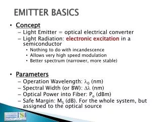
I. Introduction Electron emission mechanisms Surface barrier bending due to applied field Surface barrier Thermal excitation Photo excitation Tunneling Advantages of field emission Low energy consumption High current density Small device size (sharp tips)
I. Introduction Field Emission Applications Vacuum microelectronic device Flat panel display Conductive coating Anode Phosphor 5 mm Gate Probe Gate Emitter Emitter array Scanning probe microscope for surface imaging Pressure E-beam Focusing electrode Extracting gate d Emitter array Microsensor Cold cathode
I. Introduction Requirements for applications: Low turn-on voltage Large emission current Uniform over the array Stable emission Drawbacks of metal and silicon emitters: Anode High extracting field Sputtering damage Surface adsorption Emitter overheating Emitter
I. Introduction Diamond Field Emitter Properties of diamond Advantages for field emission Hardest known material 10,400 kg/cm2 Resistance to sputtering damage by residual gas Highest thermal conductivity 20 W/cm-oC 5 times larger than copper Efficient and fast thermal dissipation Robust performance in harsh environment Chemically inert Small effective work function Low threshold voltage for electron emission
I. Introduction Research Developments Year Highlights 1928 Field emission theory proposed (Fowler and Nordheim) 1968 First metal field emitter with self-aligned gate demonstrated (Spindt) 1976 Enhanced chemical vapor deposition (CVD) diamond developed (Deryagin) 1979 Negative electron affinity (NEA) of diamond discovered (Himpsel) 1990 Silicon field emitter array with self-aligned gate developed (Betsui) 1994 Mold-filled CVD diamond tip array fabricated (Okano) 1997 Diamond film coated silicon sharp tips demonstrated (Zhirnov) 1997 Diamond tips for tunneling microscopy developed (Albin) 1999 Diamond field emitter arrays with self-aligned gate succeeded (Albin)
I. Introduction Project Goal Design, fabricate, and characterize diamond field emitter arrays using: Silicon surface micro-machining Plasma enhanced CVD diamond Scanning electron microscopy Raman spectroscopy Optical emission spectroscopy I-V measurement
II. Field Emission Surface Energy Barrier# Combined effect Applied Field Image Charge P(x) Pe(x) Pext(x) Vacuum Level Vacuum Level Vacuum Level x x x Schottky barrier reduction f f f Feff - exF Ef Ef Ef d Surface barrier thinning #S. O. Kasap, Principles of Electrical Engineering Materials and Devices (McGraw-Hill, 1997).
II. Field Emission Field Emission Current Density T: temperature F: applied field : work function N(T,S): electron density D(F,s,): tunneling probability s: kinetic energy Fowler-Nordheim Equation# • m mass of electron • work function of the cathode • y function of F and • t(y), v(y) approximated as constants • J emission current density • e electron charge • h Planck’s constant • F electric field at cathode # R. H. Fowler and L. W. Nordheim, Proc. R. Soc. London A119, 173 (1928).
2 eV 3 eV 4 eV 5 eV 5.5 eV II. Field Emission F-N Plot Simplified F-N Equation# or Where: aemitting area f emitter work function field enhancement factor I-V Plot F-N Plot 2 eV 3 eV 4 eV 5 eV 5.5 eV (400 tip array with a tip radius of 20 nm and a field enhancement factor of 105 cm-1) #C. A. Spindt, I. Brodie, L. Humphrey, and E. R.Westerberg, J. Appl. Phys.47, 5248 (1976).
II. Field Emission Field Enhancement Factor Anode = F/ V r F: electric field at emitter tip V:voltage between anode and cathode d Spacer h Field enhancement factor for typical emitters# Cathode r #H. G. Kosmahl, IEEE Trans. Electron Devices 38 (6), 1534 (1991)
II. Field Emission Emitter Structure Effect Simulation Effect of emitter height Effect of tip radius Tip radius (top to bottom) 10 nm 20 nm 40 nm 60 nm 80 nm 100 nm Tip height (top to bottom) 4 mm 3 mm 2 mm 1 mm 0.5 mm
III. Experiments Silicon Tip Array Fabrication (a) Thermal oxidation (b) Photolithography (c) Silicon dioxide etching (f) Silicon nano tips (d) Silicon etching (e) Tip sharpening
III. Experiments Diamond Emitter Fabrication Waveguide H CH 2 4 Microwave generator Quartz window Pressure Control Plasma Gas flow meter Substrate height control Substrate Gauge Exhaust Microwave power control Valve Substrate heating control Motor Pumping System
III. Experiments Emitter with Self-aligned Gate Photoresist SiO2 Si Metal SiO2 1. Thermal oxidation and patterning 2. Silicon tip etching 3. Photoresist planarization for oxide and metal layer 5. Expose silicon tip for seeding 6. Diamond deposition 4. Photoresist etchback
IV. Results and Discussion Orientation Dependent Etching Some alkaline etchants etch various crystal planes of silicon at different etch rates <100> SiO2 <100> SiO2 <111> Silicon Silicon
IV. Results and Discussion Silicon Tip Array Wet Etching Silicon tip array etched at 90oC with various tetramethylammonium hydroxide (TMAH) concentrations 40% TMAH 25% TMAH 10% TMAH 15 minute etching Extremely non-uniform Hillocks on substrate 4 minute pinching under mask Hillock-free but non-uniform Small tip aspect ratio 10 minute pinching under mask Hillock-free and uniform Larger tip aspect ratio
IV. Results and Discussion Optimized Etching Results 2.2 m high and 1.44 m wide Aspect ratio of 1.53 1.4% non-uniformity Silicon tip array etched using: 10 m square SiO2 mask 40% TMAH at 90oC Close-up Array
h d IV. Results and Discussion Effect of Etchant Temperature Aspect Ratio = h/d Silicon tip array etched in 40% TMAH at various temperatures Height h Silicon tip arrays etched at various temperatures show similar appearance Aspect Ratio Etch rate increases with temperature Base width d The slight decrease of aspect ratio shows the etching selectivity between side planes and the base decrease with temperature
IV. Results and Discussion Effect of Oxidation Sharpening Short time oxidation (<60 min.) 60 min. 30 min. Reduces tip radius from 128 nm to 23 nm in 60 min. No significant height change 240 min. 120 min. Extended oxidation (>60 min.) No appreciable change in tip radius Tip height decreases
IV. Results and Discussion Diamond Film Growth Optimized process conditions: 35 Torr chamber pressure 600oC substrate temperature 5-30 minutes growth time Nanocrystal diamond slurry seeding 0.5-2% CH4 in H2 1 kW microwave power Close-up Array
IV. Results and Discussion Diamond film grown for 30 minutes without bias using various methane (CH4) concentrations 0.5% CH4 1% CH4 2% CH4
IV. Results and Discussion Diamond film grown for 30 minutes with -150 V bias using various methane (CH4) concentrations 1% CH4 2% CH4 0.5% CH4
IV. Results and Discussion Diamond Growth Rate Without bias High CH4 concentration increases diamond growth rate Negative bias reduces diamond growth rate With bias
IV. Results and Discussion Raman Spectroscopy Diamond film grown without bias shows a diamond peak at 1332 cm-1 and sp2non-diamond carbon around 1500 cm-1 Diamond film grown with -150 V bias shows no diamond peak but a broad band amorphous carbon signal 1332 cm-1 2% CH4 2% CH4 1% CH4 1% CH4 0.5% CH4 0.5% CH4
IV. Results and Discussion Diamond/Graphite Ratio Diamond film grown for 30 minutes without negative bias D/G ratio decreases as CH4 increases D/G ratio saturates after 1% CH4
IV. Results and Discussion Optical Emission Spectroscopy H2 CH4 CH2, CH3, CH, C2H2, Complex diamond growth process H, C, C2, … sp3 sp2 Emission intensities of CH (431 nm) and C2 (517 nm) are directly related to diamond film growth# Effects of changing methane concentration and negative bias on diamond film growth can be studied through CH and C2 emission intensity variations #M. Marinelli, E. Milani, M. Montuori, A. Paoletti, A. Tebano, G. Balestrino, and P. Paroli J. Appl. Phys., 76 (1994) 5702.
CH emission peak (431 nm) CH emission peak (431 nm) 0.5% 0.5% 1% 1% 2% 2% IV. Results and Discussion CH Emission Spectra CH emission intensity increases with methane concentration Without bias Negative 150 V bias
IV. Results and Discussion C2 Emission Spectra C2 emission intensity increases with methane concentration Without bias Negative 150 V bias C2 emission peak (517 nm) C2 emission peak (517 nm) 0.5% 1% 0.5% 2% 1% 2%
Negative bias Without bias Without bias Negative bias IV. Results and Discussion Emission Intensity Variation CH intensity increases significantly with negative bias Negative bias has no effect on C2 intensity Change in CH intensity is correlated with Raman signal for biased growth C2 intensity variation CH intensity variation
2% 1% 0.5% IV. Results and Discussion Field Emission Characteristics Diamond coated silicon tip array 5 minute film growth Without bias F-N plot I-V plot 2% 1% 0.5%
2% 1% 0.5% 2% 1% 0.5% IV. Results and Discussion Field Emission Characteristics Diamond coated silicon tip array 10 minute film growth Without bias I-V plot F-N plot
0.5% 2% 1% 2% 0.5% 1% IV. Results and Discussion Field Emission Characteristics Diamond coated silicon tip array 20 minute film growth Without bias F-N plot I-V plot
2% 1% 0.5% 2% 1% 0.5% IV. Results and Discussion Field Emission Characteristics Diamond coated silicon tip array 30 minute film growth Without bias I-V plot F-N plot
IV. Results and Discussion Field Emission Characteristics Diamond coated silicon tip array 5-30 minute film growth With -150 V bias I-V plot F-N plot 2% CH4, 5 min 2% 20 min 2% CH4, 10 min 2% CH4, 20 min 2% 10 min 1% CH4, 5 min 2% 5 min 1% 5 min
IV. Results and Discussion Effective Work Function F-N slope Field enhancement factor d = 25 m h = 2 m r = 20 nm (5 min. growth) Estimated effective work function for diamond films grown under various conditions: 2% CH4 grown 5 minutes: feff = 0.87 eV 0.5% CH4 grown 5 minutes: feff = 2.24 eV 2% CH4 grown 5 minutes with -150 V bias: feff= 2.25 eV Lower CH4 concentration and negative bias increase the effective work function of diamond film
IV. Results and Discussion Effect of Diamond Film Thickness Diamond deposition for longer time increases film thickness and the tip radius, consequently reduces field enhancement factor Diamond film grown from 5 to 30 minutes at 2% CH4 increases film thickness from 20 to 120 nm, decreasing field enhancement factor by 32% Diamond grown using lower CH4 concentration, although reducing film thickness, increases the effective work function 0.5% CH4 1% CH4 2% CH4
IV. Results and Discussion Effect of Negative Bias F-N slopes of negative biased emitters Only emitters with either short growth time or high methane concentration have measurable emission current Negative bias reduces electron emission The I-V characteristics follow the same pattern as those without bias
IV. Results and Discussion Diamond Emitters with Self-aligned Gate Process conditions: 35 Torr chamber pressure 600oC substrate temperature 5 minute growth time Nanocrystal diamond slurry seeding 2% CH4 in H2 1 kW microwave power Emitter array Close-up
IV. Results and Discussion I-V Characteristics of Gated Emitter Array Process conditions: I-V characteristics: 200 V anode voltage and 800 m spacer Onset emission at Vg = 40 V Emission current reaches 96 A at Vg= 80 V 0.87 eV effective work function 5 minute growth using 2% CH4 1.5 m gate aperture 20 nm tip radius F-N plot I-V measurement
IV. Results and Discussion Anode and Gate Current Gate current is less than 1% of anode current Same slopes for gate and anode current F-N plots Gate current is also due to field emission I-V measurement F-N plot Ianode I anode Igate Igate
V. Summary Diamond field emitter arrays on micromachined silicon are fabricated and characterized Effects of CH4 concentration (0.5-2%) Effects of negative bias (-150 V) Increases diamond growth rate Reduces diamond growth rate Increases D/G ratio No diamond Raman signal found Increases CH emission intensity but has no effect on C2 intensity Increases CH and C2 optical emission intensity Enhances electron emission by reducing the effective work function Reduces electron emission by increasing the effective work function
V. Summary Field emission characteristics 0.87 eV effective work function obtained for 5 minute growth using 2% CH4 without bias 32% decrease in field enhancement factor due to thicker film grown for 30 minutes Onset gate voltage of 40 V and 96 A emission current at gate voltage of 80 V obtained for gated emitters Less than 1% of the total emission current is collected by the gate
V. Summary Publications from this research work Journal papers: “Diamond coated silicon field emitter array” S. Albin, W. Fu, A. Varghese, A. C. Lavarias, and G. R. Myneni, J. Vac. Sci. Technol. A, 17, 2104 (1999). “Microwave plasma chemical vapor deposited diamond tips for scanning tunneling microscopy” S. Albin, J. Zheng, J. B. Cooper, W. Fu, and A. C. Lavarias, Appl. Phys. Lett. 71, 2848(1997) Conference papers: “Plasma Emission Spectroscopic Study of CVD Diamond Growth” W. Fu, A. Lavarias, and S. Albin, presented at 52nd Annual Gaseous Electronics Conference, October 5-8, 1999, Norfolk, Virginia “Field Enhancement in Silicon Nanotip Emitter Array” W. Fu, A. Varghese, presented at AVS Mid-Atlantic Chapter 1999 Spring Program Student Poster Paper Competition, May 10-12, 1999 Newport News, Virginia. (Second Prize Winner) “Diamond coated silicon field emitter array” S. Albin, W. Fu, A. Varghese, A. C. Lavarias, and G. R. Myneni, 45th AVS Internal Symposium, Baltimore, MD November 2-6, 1998