Download
1 / 16
160 likes | 277 Views
Telescope Errors for NGAO. Christopher Neyman & Ralf Flicker W. M. Keck Observatory. Keck NGAO Team Meeting #4 January 22, 2007 Hualalai Conference Room, WMKO. Telescope Wavefront Errors WBS elements. Changes in scope denoted in red 3.1.1.1.2 Telescope Dynamic Performance Data

E N D
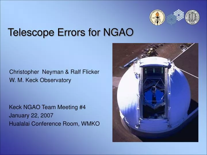
Telescope Errors for NGAO Christopher Neyman & Ralf Flicker W. M. Keck Observatory Keck NGAO Team Meeting #4 January 22, 2007 Hualalai Conference Room, WMKO
Telescope Wavefront Errors WBS elements Changes in scope denoted in red • 3.1.1.1.2 Telescope Dynamic Performance Data • Improve/document our understanding of the actual primary mirror (telescope) wavefront errors. (set spec from simulation) • 3.1.1.1.3 Telescope Static Wavefront Errors • Improve/document our understanding of the actual primary mirror (telescope) wavefront errors.(set spec from simulation) • 3.1.2.1.9 Telescope Wavefront Errors • Review new data on the telescope static and dynamic wavefront errors. Determine how and whether NGAO can correct for these errors. Determine the performance benefit of a large LOWFS patrol field to enable use of the brightest possible NGS (Pending Results of LOWFS study). Consider whether a separate sensor outside the NGAO FOV would be useful for measuring/correcting the telescope errors. Complete when impact on current Keck LGS AO system understood and impact on NGAO reviewed
Overview Slide/Outline • Telescope Dynamic Errors • Segment tilt • Full aperture tilt • Static Errors • Segment figure • Segment phasing
AO simulation approach • Simulate each effect individually, as opposed to “all in” numbers • Useful for later parameterization in wavefront error budget • Typical parameters: • NGS AO simulation • 48x48 SH (4x4 pix per sub-ap, 0.5" pixel size), • 49x49 actuators (Fried geometry) • PZT modeled influence functions • No turbulence • No noise • WFS integration time = 1ms -> integration + 1 frame delay (readout), pure integrator • A standard SVD-based wavefront reconstructor was used.
Dynamic segment errors: composite of several data sets • Segment motion datasets • Primary actuator control system (ACS) fast data capture • Erm (TMT) used ACS FDC to estimate segment motions • Highly correlated motion, looks like focus mode • Power at 29 Hz ~10-20 mas rms motion • Historical problems reconstructing wavefronts with this system • Issues documented in KAON 199 • IF accelerometers on 3 M1 segments • High noise • Some uncorroborated peaks • Calibration was uncertain • 29 Hz power similar to ACS • F. Dekens thesis • Optical measurement: 15 mas rms • Partially correlated motion • Vibration environment improved during intervening time (circa 1997)
Dynamic: Segment Errors • Adopt following baseline: • Uncorrelated segment motions • 3 peaks at 28.3, 29.06, 29.68 Hz • Total tilt 0.015 arc seconds rms • Consistent with Dekens, ACS, IF
Dynamic: Segment Errors • Adopt following baseline: • Uncorrelated segment motions • 3 peaks at 28.3, 29.06, 29.68 Hz • Total tilt 0.015 arc seconds rms • Consistent with Dekens, ACS, IF
Simulation results for dynamic segment tip tilt errors Adjusted loop gains for optimal results NGAO June proposal allocation was 23 nm Last column infinite bandwidth, no WF sensing/reconstruction error
Snap shot of simulation time series shows AO amplification Left to right: 0.5x,1x,2x,4x baseline Top: input Bottom: residual 0.5x 1x 2x 4x
AO reconstruction of segmented wavefront amplifies error Dekens conjectured that AO will increase the errors in a segmented wavefront AO sensor/reconstructor assumes continuous wave front AO correction results in tiled wavefront Amplification of coherent tilts
AO reconstruction of segmented wavefront amplifies error Dekens conjectured that AO will increase the errors in a segmented wavefront AO sensor/reconstructor assumes continuous wave front AO correction results in tiled wavefront Amplification of incoherent tilts
Tip/tilt errors • Same frequencies seen throughout observatory ~29 Hz • IF Accelerometers on M2, M3 • High noise • Some uncorroborated resonance's • Calibration • AO bandwidth error • NGS data (van Dam et al. ,Applied Optics 2004) • STRAP telemetry? (Future) • NGWFC telemetry? (Future) • AO simulation • No significant rejection below 300 Hz sampling • Poor performance on faint NGS for tracking
Static segment figures errors • CfAO poster results • UFS segment reconstruction
Static segment piston errors 100nm rms input • PCS phasing errors • 60nm (nominal) • 10nm (best algorithm) • Did not include interaction with segment figures • makes actual wavefront error higher than phasing error alone • AO stack algorithm (future) Residual Input
Summary of simulation results • Full aperture tip tilt errors could dominate tip/tilt error budget • Poor sky coverage • “Encircled Energy Science” might be impacted less • Segment motion • Acceptable error, comparable to NGAO proposal • Segment figures • Acceptable error, already included in NGAO proposal • Segment phasing • Small, interaction with figure errors not tested
References • T. Erm, “Report of the Keck mission March 10-19 Part 1. Vibrations,” Caltech, 3-31-2004 • T. Erm, “Analysis of Keck vibration data from 4/16/04, 4/29/04, 5/1/04,” Caltech, 4-16-2004 • F. Dekens, “Atmospheric characterization for adaptive optics at the W. M. Keck and Hale telescopes,” PhD thesis, UCI, 1999 • G. Chanan, et al., “The W. M. Keck Telescope phasing camera system”, SPIE 2198, 1994 • G. Chanan, et al., “Phasing the mirror segments of the W. M. Keck Telescope II: the narrow-band phasing algorithm”, Applied Optics, 2000 • van Dam, et al., “Performance of the Keck Observatory adaptive-optics system”, Applied Optics, 2004 • E. Johansson and G. Chanan, “Summary of WFS/FDC Vibration Tests”, KOAN 199, 2000.