Download
1 / 14
140 likes | 249 Views
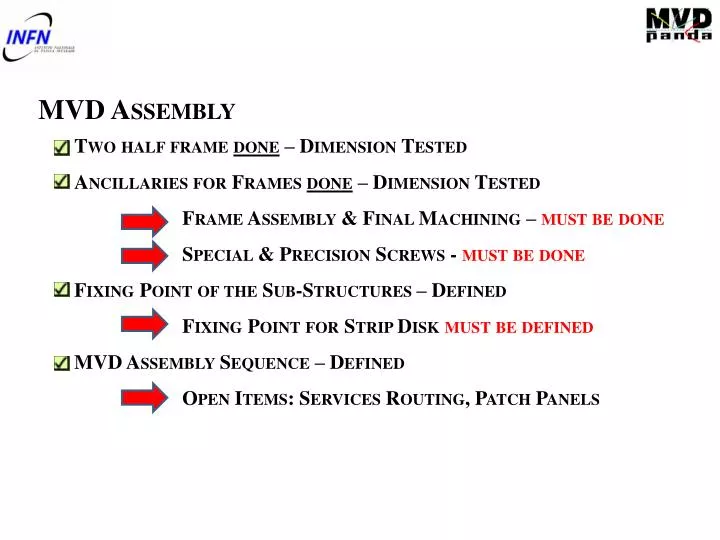
MVD Assembly Two half frame done – Dimension Tested Ancillaries for Frames done – Dimension Tested Frame Assembly & Final Machining – must be done Special & Precision Screws - must be done Fixing Point of the Sub-Structures – Defined Fixing Point for Strip Disk must be defined

E N D
MVD Assembly • Two half frame done – Dimension Tested • Ancillaries for Frames done – Dimension Tested • Frame Assembly & Final Machining – must be done • Special & PrecisionScrews - must be done • Fixing Point of the Sub-Structures – Defined • Fixing Point for Strip Disk must be defined • MVD Assembly Sequence – Defined • Open Items: Services Routing, Patch Panels
MVD Integration • MVD Aligned & Fixed on Central Frame • Ref. Bosses: two options gluing/machining • Open Item: Central Frame Definition • Critical Point: Cross Pipe Position/Geometry • MVD Final Survey • Position of target point must be defined • MVD Services Routing • Tests must be defined • Patch Panel Position must be defined • Open Item: Services Routing Outside the Magnet
MVD Pixel-Mechanics Barrel & Disks Geometry Defined Barrel & Disks Assembly Procedure Defined but NOT TESTED Barrel & Disks Cooling Tubes Assembly Defined & TestedAssemblyTooling to be defined
Services Routing - Patch Panels Very preliminary PATCH PANELS OUTSIDE STT/TPC VOLUME – PIXEL DISKS PATCH PANELS INSIDE STT/TPC VOLUME – BARREL (PIXEL+STRIP) DIFFERENT PATH FOR CABLES AND TUBES CRITICITY!!!
CENTRAL FRAME DEFINITION CENTRAL FRAME DESIGN – TARGET: RIGIDITY TARGET: MAX DEFORMATION < 50μm 1ST STEP – CURRENT DESIGN 142 μm MVD SUPPORT AREA STATIC LOAD (CROSS PIPE+MVD+STT) M55J/ROHACELL/M55J+TITANIUM (CONNECTING PART )
CENTRAL FRAME DESIGN – TARGET RIGIDITY TARGET DEFORMATION < 50μm 2nd STEP – CENTRAL WINDOWS REMOVED 124 μm MVD SUPPORT AREA STATIC LOAD (CROSS PIPE+MVD+STT) M55J/ROHACELL/M55J+TITANIUM (CONNECTING PART )
CENTRAL FRAME DESIGN – TARGET RIGIDITY TARGET DEFORMATION < 50μm 3rd STEP – ALL WINDOWS REMOVED 104 μm MVD SUPPORT AREA STATIC LOAD (CROSS PIPE+MVD+STT) M55J/ROHACELL/M55J+TITANIUM (CONNECTING PART )
CENTRAL FRAME DEFINITION NEXT STEPS: RIBS EMBEDDED INTO THE STRUCTURE STRESS INDUCED TO THE CROSS-PIPE CONNECTING PARTS MADE BY EPM203 (EPOXY/GLASS) OR CYANATE/CARBON FIBRE
Mechanics TDR • DONE & WRITTEN • Frame: • Geometry, description. • Structural constraint. • Feasibility. • Barrel: • Geometry (sensors distribution) • Physical constraint. • Support and frame connection. • Disks: • Geometry (sensors distribution) • Physical constraint. • Frame connection. • TO BE DONE • Assembly sequence. • Assembly tools. • End stave electronics boards support definition. • Mechanical integration with strip parts (barrel & disks)
MVD Pixel-cooling carbon foam tested disks cooling Defined & tested, small disks to be optimized barrel cooling Defined &tested,to be optimized Open Item: test with master bond glue cfd simulation cooling plant-first drafs of pixel parts
Cooling TDR • DONE & WRITTEN • Pixel cooling system: • Pixel power • Thermal request • Working condition • Test on carbon foam (Young modulus and thermal conductivity at different radiation fields) • Disks cooling system: • Description • Fem analyses and test results on prototype • Pressure drop • Barrel cooling system: • Description • Fem analyses and test results on prototype • CFD simulation • Cooling plant: • Description • Pixel modularity • First drafts • TO BE DONE • Tests with Master Bond glue • Cooling for the End stave electronics boards • Strip part integration in the cooling plant • Final design of the cooling plant