Download

1 / 23
230 likes | 490 Views
Synthesizing SRAM timing and Periphery using Synopsis. By: Jim Boley. Previous work. Bitcell array layout complete DRC clean, LVS…not working Timing and decoder simulated and synthesized. 53.84 μ m x 15.12 μ m = 814.1 μ m 2. Timing/Periphery Synthesis. } . BL Drivers . }. BLB Drivers .

E N D
Synthesizing SRAM timing and Periphery using Synopsis By: Jim Boley
Previous work • Bitcell array layout complete • DRC clean, LVS…not working • Timing and decoder simulated and synthesized 53.84μm x 15.12μm = 814.1μm2
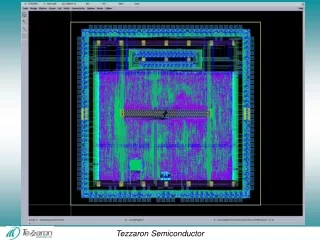
Timing/Periphery Synthesis } BL Drivers } BLB Drivers <- Decoder output
Constraints file • set_driving_cell- sets input fan in • set_load- sets output fan out set_driving_cell -lib_cell NBUFFX16 -pin Z [get_portsclk] set_driving_cell -lib_cell NBUFFX4 -pin Z [get_ports {read enable}] set_load[expr 16 * [load_of saed90nm_typ_ht/INVX2/INP] ] [all_outputs]
Final Steps • Finish bitcell array- (power grid, add body contacts, add pins) • Convert layout into a Milkyway Library • Create final top level verilognetlist • Place and route using ICC
Step 1 • Two options for exporting the layout: • GDS (Stream) • LEF
Step 2 • Create new milkyway library
Step 3 • Import GDS or LEF • Cell Library -> Stream In • Cell types: standard cell, pad cell, filler cell, macro. If blank, default is std cell • Layer file- converts GDS to milkyway. If none, layer names defined in GDS are retained by milkyway
Step 4 • Create the FRAM view, used for place and route • For macros use Cell->Make Macro Abstract
Step 4 • Extract blockage- allows you to completely block certain routing layers or keep all blockage information • Extract pin by text- easier if text layer matches pin layer
Final Steps • Set PR Boundary • Cell Library->Set PR Boundary • Define unit tile wire tracks • Wire Tracks-> Define Unit Tile Wire Tracks
Create Top Level Verilog module top ( adr, read, enable, clk, data_in, BL, BLB, WL, data_out ); input [3:0] adr; input [15:0] data_in; output [15:0] BL; output [15:0] BLB; output [15:0] WL; output [15:0] data_out; input read, enable, clk; timing_1 tim (.adr(adr), .read(read), .enable(enable), .clk(clk), .data_in(data_in), .BL(BL), .BLB(BLB), .WL(WL), .data_out(data_out) ); bitcell_array bitcells (.WL(WL), .BL(BL), .BLB(BLB)); endmodule
Reference the Milkyway Library Definitions.tcl: create_mw_lib -technology ../ref/techfiles/saed90nm_icc_1p9m.tf \ -mw_reference_library {../ref/saed90nm_fr bitcell_array} \ -hier_separator {/} \ -bus_naming_style {[%d]} \ -open ./SRAM_TOP set tlupmax "../ref/tluplus/saed90nm_1p9m_1t_Cmax.tluplus" set tlupmin "../ref/tluplus/saed90nm_1p9m_1t_Cmin.tluplus" set tech2itf "../ref/tluplus/tech2itf.map" set_tlu_plus_files -max_tluplus $tlupmax\ -min_tluplus $tlupmin\ -tech2itf_map $tech2itf import_designs-format verilog\ -top top \ -cel top {../source/top.v} source ../source/constr.sdc
Load setup.tcl & definitions.tcl • Tool will complain that the bitcell_array does not have a corresponding logic cell description…this is okay
ERROR! Unable to place bitcell array • Unable to get past this error • Tried creating milkyway library from LEF file, but icc was not able to recognize ports
Periphery placed and routed • Was able to place and route periphery cells • Final dimensions: 127um x 34 um • Original bitcell array size: 53.84μm x 15.12μm • Synthesized periphery 5.3X larger than bitcell array
Pitch Matching • Goal: 1x1 matching of periphery cells to bitcells • Vertical pitch of std cell 3x that of bitcell • Solutions: place 3 std cells horizontally • Increase pitch of bitcell • Better solution: create standard cells whose pitch match the bitcell
Conclusions • Standard cell library cells are not suited for SRAM periphery • Periphery usually consumes on 20% of total area because it is pitch matched to the bitcells • Place and route tool could be useful for doing top level routing(assuming placement information could be easily passed to the tool)
Why I didn’t like Synopsys • No online forums for answering questions (like cadence has) • Nothing worked the first time • Spent 70% of my time debugging the tool, some problems could not be overcome • Tech support infrastructure not adequate (i.e. working tutorials, wiki FAQs, students with experience) • Conclusion: changing tools = huge start up cost