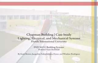
Case Study Abstract Summary
Case Study Abstract Summary. This case study analyzed the user-efficiency of the electrical and lighting systems in the Chapman Building. The building site was observed and analyzed and the construction documents were closely examined.

Case Study Abstract Summary
E N D
Presentation Transcript
Case Study Abstract Summary • This case study analyzed the user-efficiency of the electrical and lighting systems in the Chapman • Building. • The building site was observed and analyzed and the construction documents were closely examined. • Based on this information, hypotheses were established regarding the impact of the electrical and lighting systems upon the users of the Chapman Building. • The study consisted of a random sample of twenty-five students, administrative, maintenance, and other building staff. • The findings revealed that the lighting and electrical systems appropriately meet the needs of its users. However, the methods in which these findings were determined need some adjusting. Several pages of building plans were unavailable, and the sample of respondents may have been too small to yield accurate results. • Ultimately, specific user-needs were successfully identified and the systems’ performance measured to be appropriate.
Lighting Types Cove lighting is located at the front entrance of the Chapman Building giving an inviting feel. The lighting energy efficient and turns on as it gets darker outside. The cove lighting is on the inner circle of the ceiling element giving it a nice glow, but it does not have a continuous source of light along the entire edge. (left) Cove lighting in the front entrance is turned off when there is a sufficient amount of daylight within the space. This is a way to be more energy efficient and take advantage of the natural light provided in south Florida. (left) Key Plan Figure 5. Figure 1. Figure 2. Dim indirect lighting with an ambient glow. It is well maintained, but some lights are not functioning because bulbs have blown out. The lights create a sense of repetition and pattern in the ceiling. (above) Figure 6. Cove lighting is located above the coffee shop and pendant lighting hangs above the countertop. The lighting is interesting and well maintained. It draws people into the space creating a pleasant atmosphere. The combination of task and ambient lighting is essential for the customers as well as the employees. (above) Reflected Ceiling Plan, First Floor Building 1 Spot lights are located on the perimeter of the ceiling in a fine encasing. The lighting is most functional for night-time use since the space has sufficient daylight entering on a sunny day. The lights are placed on an unusual slant because of the way the ceiling is sloped, this makes it somewhat unique and interesting. (left) Figure 3. Cove lighting located throughout building 1’s corridor highlights the AC vents along the wall. The lighting seems to be unnecessary and not aesthetically pleasing (above) Figure 4.
Lighting Types Elevator Mechanical Room Electrical Room & Telecommunications Room Restroom Lighting Key Plan Details of Toilet Rooms : First Floor – Building 2 Detail of Toilet Rooms : First Floor – Building 1 Reflected Ceiling Plan, First Floor Building 1 Tubular lighting within a metal grid. The lighting is inconsistent because of different color bulb temperatures. The combination of both lighting types makes for an unflattering awkward experience. The sink and stalls both have this awkward lighting condition. (left) Four fluorescent tubular light panels are located above the lockers. A light-saving switch controls the number of lights that are on at a single time. If the orange dot on the switch is on, only one fluorescent tubular light panel is on, and when it is off then all four fluorescent tubular panel lights are on. The lighting is both functional and energy saving, while also providing a level of comfort and an inviting ambiance for the locker room. (left) Figure 9. Figure 8. Figure 7.
Classroom and Auditorium The classroom has fluorescent tubular lights and recessed cans. It has large windows along the wall to provide natural light. The lighting does not put glare on the computer screens. There is enough natural light that at certain times the lights remain off and students do their work efficiently. (left) Key Plan Elevator Mechanical Room Electrical Room & Telecommunications Room Figure 12. Figure 10. Recessed canned lights along with spot lights are located on the ceiling of the auditorium. Natural lighting flows into the space through side windows. The orientation of the windows causes a problem since the light directly hits the projection screen, and causes glare. (above) Figure 11. Figure 13. In the classroom there is a group of electrical switches and outlets. All of the electrical devices are in good condition and easily accessible due to their convenient location near the front of the room. (above) Handicap accessibility in the business auditorium was what appears to be thought of later in the deign, as you can see all the mechanical workings located on the side of the wall. (above) Reflected Ceiling Plan, Second Floor Building 2
Natural Lighting and Artificial Lighting Florescent light tubes are used to light the Electrical Rooms. These lights are more energy efficient and produce less heat than incandescent lights. They also have a longer life and require less maintenance. (left) Figure 17. Figure 15. Florescent light tubes are used in the Control Room. These lights are more sustainable and last longer than incandescent lights. The light tubes are cast within a panel system in the ceiling, making them more aesthetically pleasing than if they were left exposed. (left) Clerestory windows are located in the second floor of the Chapman Building. They provide a good source of natural light to the office spaces, but at the same time, they do not expose the spaces to too much heat. (above) Figure 14. Natural lighting enters the space through the floor-to-ceiling windows near the entrance to the Chapman Building. The lighting is functional and provides a sense of wellness. It also creates a bright ambience which gives a sense of pleasantness to the entrance of the building. (above) Figure 18. Fluorescent lighting located in the office space directly outside of the elevator. The light bounces off towards the ceiling and the perforation diffuses the light to produce ambient lighting. (left) Figure 16. Conference room has indirect lighting, and roller shades to decrease the amount of morning light that enters the room since the windows are facing east. (above) Figure 19.
Electrical and Mechanical Room Elevator Mechanical Room Electrical Room & Telecommunications Room Key Plan Figure 21. Figure 20. Electrical room, located near the docking station for easy access. FPL feeds the power to this room and it is distributed to the rest of 1st and the 2nd floor. (above) Electrical conduit running through the ceiling. The connections are well organized. (above) Floor Plan, First Floor Building 1 Figure 22. Figure 23. Electrical box in the 2nd floor electrical room. It is well organized and there is plenty of room to work in. (above) Electrical circuitry in the mechanical room. Allows for easy access and is located and a reachable height. (above) Floor Plan, Second Floor Building 1
Electrical Room and Elevators Elevator Mechanical Room Electrical Room & Telecommunications Room Figure 26. Transformer boxes connecting multiple wire connections. Heavy machinery; located on a shelving unit up above. (above) Figure 24. Figure 25. Circuit breaker box, located on the right side of the door. The box is well organized and clearly labeled. (above) Multiple wiring connections for several electrical systems in the room. The boxes get extremely warm and generate a lot of heat in the room. Well organized and labeled. (above) Key Plan Floor Plan, Second Floor Building 2 Floor Plan, Third Floor Building 1 Figure 28. Figure 27. Single fluorescent tubular lighting. The small space feels too overpowered with only one light location and it shows the dirt on the ceiling panel. (above) The elevator is well kept and properly maintained. (above) Key Plan
Mechanical Room Key Plan Figure 30. Figure 31. Figure 29. Mechanical room filled with different types of equipment such as computers, t.v. screens, cameras, and tons of different wires. The room is very cramped and cluttered, not allowing for its occupants to have easy access. (above) Electrical wiring above ceiling panel. Seems to be very heavy, disorganized and not very accessible. (above) Electrical equipment used for powering up most of the computers in the building. (above) Figure 34. Figure 33. Figure 32. Fluorescent lighting above multi media storage unit is being used to illuminate the mechanical room. (above) Air conditioning panels located in the mechanical room for different classrooms. (above) Computer monitor used to record classroom sessions. Multiple wire connections all scattered along the room making it unsafe, especially incase of an emergency situation. (above) Detail of Mechanical/Control Room
Electrical outlets and Exit Signs An electrical outlet that is not covered and could be hazardous to students and faculty. The outlet is not functional and the use is not clear. The location of this open, unsecure outlet may be dangerous if touched by anyone. (left) Figure 36. Figure 37. The outlets are very unclean and possibly hazardous. They are very functional and accessible for students to use for computers or any electrical devices. However, the location of these outlets may cause problems as far as tripping over the cables, or even the lid of the outlet. There are also not an adequate number of outlets for all students at certain times in the day. (above) Outlet plugs and wiring connections located on the ceiling in the student lounge. The connections are well secured in bundles and easily accessible for maintenance or technicians. The outlets are placed in a good location near the TV's, and are neatly grouped together to make it appear almost invisible. (above) Figure 35. The outlets look like dual telephone jacks and are in new condition. They are located on the interior wall of the corridor. This might not be the most appropriate location for functional use, due to circulation flow. (left) Wall mounted exit sign with lights to guide above, and ceiling mounted exit sign. Both figure and figure light up with the word “EXIT” in red. The exits signs are in new condition with appropriate locations and adequate lighting. They are functionally lit in case of an emergency, or in the event that the power goes out. (left) Figure 38. Figure 39. Figure 40.
Electrical Outlets, Security Accessories, and Appliances Figure 43. This is the faculty lounge, located in building one. Appliances are available for the daily use of office staff and professors. (above) Figure 41. Figure 42. Card swipe is necessary to access certain areas in the building such as some of the conference rooms, offices and auditorium. This system prevents property damage and stealing of equipment. (above) Outdoor floor lights located outside all along the courtyard area. (above) Figure 46. Figure 44. Figure 45. Electrical outlets located on the light posts near the side-walk in the courtyard of the Chapman Building. (above) The ice machine is located in the catering space of the conference room. It is conveniently placed to be very accessible, and in good condition. (above) Fire alarm box with audio and visual alert system. Located on the exterior corridor wall of the second floor of the building near classrooms. (above)
Users-Type Every user interacts with the system components at all times in one way or another. Whether the user is a full-time student, a member of the custodial team, a professor, or is simply “walking though” to enjoy the air conditioning, they are all using the lighting, electrical, and mechanical systems. Figure 47. Figure 48. Students : This group is comprised of graduate and undergraduate students studying business and international business, as well as students from other majors. The majority of students, however, are business students. Faculty: The faculty occupies the entire second floor in building two. The faculty consists of teachers, professors, advisors, etc. Administrative Staff: Office Staff includes secretaries, catering coordinators, and other clerical staff. Maintenance Staff: The maintenance team is comprised of maintenance techs and custodial staff. Café and IT Staff: Java City employees and Information Technology staff comprise this category. Other: The last group includes visitors, guest speakers, and other students casually using the café or courtyard. Students use the computer lab for leisure, and for technology classes. They can also view the Stock Exchange tickertape. (above) This student is a business student who is studying and watching the news in the lounge area. (above) Figure 50. Figure 49. In the cafe lounge area, this student hooked up his laptop in one of many personal internet outlets. (above) This student is a member of the IT staff, working in his office located inside the computer lab. (above)
Summary of Hypotheses and Results by User-Type • Administrative: • Due to the clerestory windows and abundant office windows, the administrative staff receives sufficient natural light, which is beneficial to their content. Overall, they agreed that they had adequate natural and ambient lighting, resulting in a strong sense of well-being, leading to more job satisfaction. • The technological infrastructure is adequately organized and reliable, allowing the staff to carry out their responsibilities without interruptions. The telecommunication systems are adequately organized to meet the needs of administrative staff. Unanimously, they agreed that their technological capabilities exceed their expectations. • Student: • Despite internal lighting systems in the Café and lounge area, excess sunlight creates glare, causing frustration and increasing the likelihood of leaving this environment for a more comfortable one. The majority of students agreed that the glare makes studying more difficult, especially when using a computer, causing them to squint or leave during peak sunlight hours. • The number of electrical outlets is inadequate and spaced in an unnatural fashion in relation to the furnishings. Students concurred that although there are many floor outlets, they are not spaced well and can cause a tripping hazard. • Maintenance: • Although the maintenance staff is supposed to change the light bulbs on a schedule, this does not always occur due to time constraints or simply over-looking it. Although we believed this would frustrate any user, the combination of natural light and the internal lighting system were more than sufficient should a bulb or two need changing.
Lighting System Final Analysis • According to our interviews of administrative staff members, natural lighting is effective in promoting well-being and productivity. • Artificial lighting was a complement to the natural lighting in the office spaces. • People who work in cubicles or offices feel that the amount of lighting they receive is appropriate for the • environment. • Glare is a major issue in the Java City lounge area. • The lighting system was well-maintained and offered flexibility for users during the changes in solar patterns. • Artificial lighting is provided in all of the spaces, mostly with fluorescent tubes, but in few cases incandescent lamps. • The maintenance staff efficiently changes the light bulbs when they are burned out to avoid interruptions to the users, although it is not done on a regular schedule.
Electrical, Telecommunication, and Mechanical Systems Final Analysis • Electrical System: • The there are enough outlets located in different places in the building, but the outlets in the Java City lounge • are not placed appropriately in relation to furnishings. • Floor-outlets may cause a tripping hazard for people working or moving about this space. • Telecommunication/Mechanical System: • Technicians are available, if necessary, to correct any interruptions in service immediately, avoiding any negative • impact upon the users. • They are also very conscious about their impact on the faculty and students, keeping the issues to a minimum. • Most staff members are satisfied with the telecommunications system. • Several appliances in the kitchen/pantry that were in working condition, used mainly by the catering services • and some employees. • The HVAC systems work efficiently, although students may feel the rooms are cold. The static-temperature is • controlled at an off-site location and cannot be changed for specific.
Strengths and Limitations of the Case Study and Analysis • Limitations: • The limitations of the Project, System, and User Identification were largely due to issues concerning the availability of certain plans, elevations, etc. • The small timeframe given for the tour made it difficult to ask every question we had. • UTS-owned telecommunication rooms were unavailable for viewing. • The interviews were supposed to prove or disprove our theories. However, the interviewees did not necessarily provide adequate information to definitively state whether the hypotheses were correct or not; sometimes we had to make assumptions. • The sample of approximately thirty people was too small to accurately represent the views of every user. • Strengths: • Having the construction documents available, knowing the key building components, and categorizing the user-types helped us in being prepared for the Site Observation and Building Tour phases. • We were able to pinpoint certain locations of interest on the plans in preparation for the following portions of the study. • The most valuable aspect of the case study, the Building Tour allowed us to physically visit the spaces, ask our guide pertinent questions, and take photographs or our systems’ components. • Forming the hypotheses and interview questions was helpful in determining the experiences of the specific users; it allowed us to view the system components from their perspectives.
What Could We Have Done Differently? • As a whole, our research and analysis exceeded our expectations, but there are a few areas in which there is room for improvement: • In order to obtain more accurate results from our interviews, the respondents should have been pre-screened; we should have only interviewed students who could answer in full. • To guarantee a more-useful pool, we could have distributed a quick “yes or no” questionnaire, which would either qualify or disqualify the candidates for the interview. • Increasing the amount of time and number of people interviewed would have made our results more accurate and more representative of the users as a whole.
References • Binggeli, C. (2010). Building systems for interior designers. Hoboken, New Jersey: John Wiley & Sons, Inc. • Brown, K. (personal photographs, September 7, 2010) • Jyselle, V. (personal communication, September 29, 2010) • Kpf's New Chapman Graduate School of Business Opens in Miami. Retrieved August 25, 2010 from World Architecture • News Website: http://www.worldarchitecturenews.com/index.php?fuseaction=-wanappln.projectview&upload_id=1951 • Meignen, P. (personal communication, September 29, 2010) • Nykolaiszyn, J. (personal communication, September 29, 2010) • Schnog, G. (personal communication, September 29, 2010)
Thank you! Ready for the quiz?
Quiz Questions • 1. What kind of lighting is provided in the locker rooms? • Pendant Lighting • Fluorescent Light Tubes • Cove Lighting • Down Lights • Natural Lighting • 2. TRUE or FALSE. According to the users, most staff members are satisfied with the telecommunications system. • 3. What is the main reason why floor outlets should be replaced by wall outlets? • They are aesthetically unattractive • They are difficult to replace • They cause tripping hazards • They are hard for maintenance to clean • They easily break • 4. Who are the main users of the space? • Faculty • Office Staff • Maintenance Staff • Java City Staff • Students • 5. TRUE or FALSE. According to the users, natural lighting was not efficient in providing a sense of well-being and increasing their productivity.