Download
1 / 4
40 likes | 164 Views
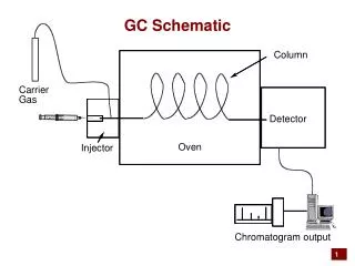
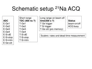
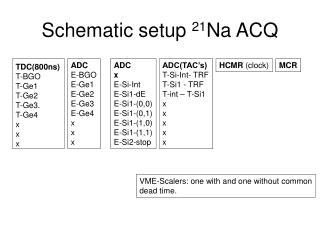
This document outlines the schematic setup for measuring 21Na using advanced detection techniques. It includes Time-of-Flight (TDC) and Analog-to-Digital Conversion (ADC) components, configured to capture data from various detectors such as BGO and Ge. Key elements of the setup involve T-Si planes, dead-time measurements, and scaling modules for accurate timing and signal processing. The system also features triggers, clock management, and facilities for common dead time analysis, all aimed at enhancing the precision in particle detection and timing.

E N D
Schematic setup 21Na ACQ TDC(800ns) T-BGO T-Ge1 T-Ge2 T-Ge3. T-Ge4 x x x ADC E-BGO E-Ge1 E-Ge2 E-Ge3 E-Ge4 x x x ADC x E-Si-Int E-Si1-dE E-Si1-(0,0) E-Si1-(0,1) E-Si1-(1,0) E-Si1-(1,1) E-Si2-stop ADC(TAC’s) T-Si-Int- TRF T-Si1 - TRF T-int – T-Si1 x x x x x HCMR (clock) MCR VME-Scalers: one with and one without common dead time.
scaler TFA CFD Fixed delay TDC1 BGO Ge1 : Ge4 ADC2 BGO Ge1 : Ge4 MA stretcher 4x PA Ge1 MA Ge2 Ge3 TFA CFD or Ge4 Shield Ge trigger and scalers Ge1 Ge2 Ge3 Reserve Not used(?) Ge4 Analogue + time signals Ge
TAC start stop RF CFD ADC3 Si-int plane PA TFA CFD TAC start stop MA Si-dE Si1 (300 um) Focal pl PA TAC start stop TFA CFD MA ADC1 Amp/Shp ch0 ch1 ch2 ch3 4-Pos Si-stop Si2 (150 um) Focal pl PA Si2 trigger TFA CFD MA Analogue + time signals Si
scaler common start TDC Ge slow gate TAC ADC slow gate ADC Ge slow gate ADC Si dead time measurement dual timer start noto out VME scaler 1 MCR 2 dead time (TM) coinc win (FC) 4 fi/fo T-int start noto out T-Si1 VME scaler 2 fi/fo T-Si2 or Ge HCMR OPA1 out to cyclo: beam off trigger logic