Download

1 / 19
200 likes | 356 Views
Hardware-in-the-Loop Development and Testing of New Pitch Control Algorithms EWEC 2006 Athens Martin Geyler, Jochen Giebhardt, Bahram Panahandeh Institut für Solare Energieversorgungstechnik (ISET e.V.) Phone: +49-561-7294-364 e-mail: mgeyler@iset.uni-kassel.de. Project Objectives.

E N D
Hardware-in-the-Loop Development and Testing of New Pitch Control Algorithms EWEC 2006 Athens Martin Geyler, Jochen Giebhardt, Bahram Panahandeh Institut für Solare Energieversorgungstechnik (ISET e.V.) Phone: +49-561-7294-364 e-mail: mgeyler@iset.uni-kassel.de
Project Objectives Development of advanced pitch control algorithms for load reduction in large wind turbines Project Partners • Individual blade pitch control • compensation for unsymmetrical inflow conditions due to turbulence or deterministic effects • active damping for tower and blades • Modular controller design • Development of safety algorithms • stability monitoring, • handling of sensor faults • Identification of requirements for the pitch system using a Hardware-in-the-Loop test bed setup • dynamics, • loads, wear, • power consumption, thermal losses, • load sensors • communication requirements
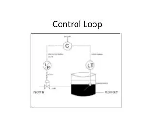
Control Problem Schematic of Control Loop
Test Bed: Laboratory Setup Controller Rack with Simulation PCs Pitch Drive Inverter Cabinet Load Drive Inverter Cabinet Host PC Load Machines Pitch Motors
Real-Time Simulation: Overall Wind Turbine Model Block structure of Simulink model
Real-Time Simulation: Mechanical Model (1) Multibody approach: • 14 rigid bodies connected by joints: • Universal joints with torsional stiffness and damping representing flexibility of the structure • Revolute joints with external torque input representing actuators • fully recursive algorithm: „Method of Articulated Inertia“: • tree-like structure is exploited • avoids need for inverting large mass matrices • O(N) method: computational effort increases linearly with number of DOF • Mass forces (gravity, inertia) inherently included by the algorithm. • Solver: 3rd-order Runge-Kutta solver at 1ms time step • ca. 450 µs calculation time on Athlon 4000+ PC Mechanical model
Real-Time Simulation: Mechanical Model (2) • Parameters for multi body model were calculated using a optimisation algorithm to find a best fit to a given finite elements (FE) model: • Step: Optimisation of joint locations in order to allow for best representation of first 3 mode shapes • Step: Optimisation of stiffness parameters and joint twist angles in order to fit eigen frequencies and mode shapes • Validation: Comparison of static deflection due to a constant line load (blade) or constant tower top force 1st mode and static deflection of simplified blade model with 2 rigid sections; Comparison with FE model Mechanical model
Real-Time Simulation: Pitch System Model Load torque reference values for load drives will include the following effects: • pitch gear ratio 1:1000 • tooth clearance at fast side of pitch gears • blade bearing friction • DRE/CON-formula for large bearings: • MR = µD/2 * k * M blade root • Four point contact bearings: • µD = 0.006, k = 4.37 • Components for axial and radial force have been neglected. • changing inertia due to blade deflection inherently included by mechanical model Example simulation for pitch load situation in turbulent wind conditions
Real-Time Simulation: Aerodynamic Model (1) • Blade Element Momentum Theory (BEM) • 12 blade elements per blade • semi-empirical corrections: state-of-the-art implementation of • dynamic inflow • yawed inflow • dynamic stall • total 240 aerodynamic states • Solver: simple Forward-Euler integration at 1ms time step • calculation time ca. 45 µs on Athlon 4000+ PC
Real-Time Simulation: Aerodynamic Model (2) • Dynamic Inflow Model (ECN): • Local inflow condition at blade sections depend on free wind speed and load situation of the rotor in a dynamic manner. • Example: Overshoot in blade root bending moment for fast step on pitch angle Tjaereborg Experiment Simulation
Real-Time Simulation: Aerodynamic Model (3) • Dynamic Stall Model (Beddoes-Leishmann-Type): • Effect: dynamic lift forces can be considerable bigger than predicted by stationary cL--curve for fast changes in pitch angle. Simulation Measurement (Risø)
Real-Time Simulation: Turbulent Wind Field Input (1) • 2-D turbulent Wind Field is simulated off-line and read from a file during real time simulation reproducible time series • 8 x 8 points in the rotor plane, • linear interpolation • only mean wind direction • Method by Mann • wind field is assembled in a 3D-box by means of inverse FFT • Fourier Coefficients calculated from spectral-tensor ( only 11 used ) • „frozen turbulence“ : dimension L1 is used as time axis • Parameter fitting to Kaimal spectrum • Input parameters: • mean wind speed, • mean wind shear, • turbulence intensity • Extreme gust events can be embedded into stochastic turbulent wind field: • Most likely gust shape calculated from correlation matrix R and a given criterion e.g. total jump in wind speed at given location
Real-Time Simulation: Turbulent Wind Field Input (2) Averaged auto-power spectrum for simulated wind fields Example for extreme gust event Criterion: v = 10 m/s, t = 16 s, location
Real-Time Simulation: Visualisation • 3D visualisation tool for motion and load situation of simulated wind turbine • VRML based • Visualisation coupled to real-time simulation via TCP/IP based communication channel Visualisation with VRML
First Results (1) • Algorithm for yaw and tilt moment compensation implemented and tested • (simulated) 1p component in flapwise blade root bending moments is almost cancelled, • pitch drive rating seems sufficient for producing required 1p cyclic pitch offsets, however, considerably increased motion as compared to normal collective pitch operation • simple fuzzy scheme for supervision and controller gain adjustment simulated reduction in 1p component of flapwise blade root bending moment
First Results (2) Measurement of Pitch Drive Load Torques
Conclusions • Hardware-in-the-Loop test bed for Pitch Drives has been developed and successfully taken into operation. • Real-Time Simulation Environment allows for providing realistic load conditions as well as all required feedback signals to the tested Pitch Control System. • First simulation results and measurements for a Yaw- and Tilt-Moment Compensation Controller (Proof-Of-Concept). • It is believed, that the test bed will greatly improve the understanding of the system aspects of advanced pitch control strategies. Thank You.