Download
1 / 7
70 likes | 84 Views
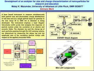
Water inlet structures to rearing units at fish hatcheries are used to maintain continuous water flow,<br>prevent the introduction of undesirable organisms and organic debris, and deter escapement by<br>the fish being reared. This paper describes a novel pond water inlet structure that not only kept<br>the water flowing unimpeded, but required considerably less labor to maintain than other designs.<br>This relatively simple aluminum structure consisted of a collar for attachment to the inflow pipe<br>and a terminal splashplate. The splashplate was perpendicular to the inflow pipe during normal<br>operations to both prevent fish from jumping into the inflow pipe and aerate the incoming water.<br>The splashplate was designed to swivel upward to allow for the efficient removal of any debris,<br>such as branches or leaves. Use of the inlet structure consistently increased incoming dissolved<br>oxygen levels, which were as low as 4.75 mg/L, to over 9.0 mg/L. Increased efficiencies during<br>hatchery operations can be realized by using this inexpensive and relatively easy-to-construct inlet<br>structure.

E N D
E-ISSN 2149-0236 FULL PAPER TAM MAKALE A NOVEL TROUT POND INLET STRUCTURE Eric Krebs1, Alissa M. Muggli2, Joseph M. Barnes2, Michael E. Barnes1 Cite this article as: Krebs, E., Muggli, A.M., Barnes, J.M., Barnes, M.E. (2018). A Novel Trout Pond Inlet Structure. Journal of Aquaculture Engineering and Fisheries Research, 4(2), 73-80. 1South Dakota Department of Game, Fish, and Parks, McNenny State Fish Hatchery, 19619 Trout Loop, Spearfish, South Dakota 57783, USA ABSTRACT Water inlet structures to rearing units at fish hatcheries are used to maintain continuous water flow, prevent the introduction of undesirable organisms and organic debris, and deter escapement by the fish being reared. This paper describes a novel pond water inlet structure that not only kept the water flowing unimpeded, but required considerably less labor to maintain than other designs. This relatively simple aluminum structure consisted of a collar for attachment to the inflow pipe and a terminal splashplate. The splashplate was perpendicular to the inflow pipe during normal operations to both prevent fish from jumping into the inflow pipe and aerate the incoming water. The splashplate was designed to swivel upward to allow for the efficient removal of any debris, such as branches or leaves. Use of the inlet structure consistently increased incoming dissolved oxygen levels, which were as low as 4.75 mg/L, to over 9.0 mg/L. Increased efficiencies during hatchery operations can be realized by using this inexpensive and relatively easy-to-construct inlet structure. 2Engineering Benedictine College, 1020 N 2nd Street, Atchison, Kansas 66002, USA Department, Submitted: 28.06.2018 Keywords: Water inlet structure, Splashplate, Trout rearing, Aeration Accepted: 14.09.2018 Published online: 21.09.2018 Correspondence: Michael E. Barnes E-mail: mike.barnes@state.sd.us Journal abbreviation: J Aquacult Eng Fish Res
Journal of Aquaculture Engineering and Fisheries Research, 4(3), 120-126 (2018) Journal abbreviation: J Aquacult Eng Fish Res Introduction clog, fish escapement out of the pond is more likely than if using a screen (Piper et al., 1982). Fish hatcheries require large amounts of water (Lekang, 2013). For intensively-cultured fish with relatively high oxygen demands such as trout and salmon, the supply of fresh water needs to be continuous when these fish are reared in flow-through ponds (Piper et al. 1982). If the water originates in open springs or arrives to rearing units, such as earthen ponds, in open channels as is relatively common (Stickney, 1994), leaves and other debris can impede incoming water flow, particularly if there is a screen or valve at the point-of-delivery to the pond (Leitritz and Lewis, 1976; Helfrich, 1999). At McNenny State Fish Hatchery, rural Spearfish, South Dakota, USA, one of the trout ponds receives water from an open spring through a pipe. Originally, the water inlet consisted of a wooden head box (Figure 1), which was eventually replaced with a 30 cm diameter cast iron pipe with holes cut into it with an acetylene torch (Figure 2). These holes were approximately 3 cm in diameter to allow the water to flow out and also prohibit trout from jumping into the supply water line. This inlet design proved extremely laborious however, because the holes were prone to plugging with leaves, aquatic vegetation from the springs, and other debris. Additionally, the holes could not easily be cleaned. An alternative water inlet structure was clearly needed. Materials and Methods Screens are routinely used to both prevent fish movement out of rearing ponds, as well as preclude the introduction of undesirable organisms, including fish, and organic debris (Leitriz and Lewis, 1976; Piper et al., 1982). Various pond inflow pipe screening devices have also been developed to add oxygen through passive aeration (Moore and Boyd, 1984; FAO, 2018), but these designs typically do not consider plugging or fish movement issues. Head boxes are also used at pond inlets, and while they will not typically The existing cast iron pipe was removed and replaced with a novel pond inlet structure constructed primarily with 0.635 cm plate aluminum grade 6061 (Figure 3). The new structure consisted of an aluminum collar for attachment Figure 1. Wooden headbox with a metal splashplate initially used as a pond inlet at McNenny State Fish Hatchery (note the plastic mesh attached to the headbox to try and prevent fish from ascending into the inflow pipe, as well as the fish jumping up the turbulent water towards the headbox). 121
Journal of Aquaculture Engineering and Fisheries Research, 4(3), 120-126 (2018) Journal abbreviation: J Aquacult Eng Fish Res Figure 2. Cast iron pond inlet used as a pond inlet at McNenny State Fish Hatchery. This image shows only one-half of the symmetrical structure. Figure 3. Novel inlet structure with splashplate in the down position. to the incoming pipe along with a terminal splashplate (Figure 4). The inlet structure was attached to the pipe by drilling five 1.3 cm holes (two on each side and one on the top) through the aluminum collar and plastic pipe, inserting 1.27 cm diameter (3.8 cm long) bolts, and securing the bolts with 1.27 cm nuts. The splashplate was designed to swivel upward so as to allow for quick and easy removal of any debris that might arrive via the inflow pipe and remain lodged with the splashplate in the down position (Figure 5). The angle of the splashplate was 130°, with a distance of 19.2 cm from the end of the inlet pipe. Two 9 cm long pieces of 3.8 cm 122
Journal of Aquaculture Engineering and Fisheries Research, 4(3), 120-126 (2018) Journal abbreviation: J Aquacult Eng Fish Res Figure 4. Schematic of the novel inlet structure. Figure 5. Schematic of the inlet structure with the splashplate in the up position, indicating the swivel point and non- plate aluminum features. aluminum angle were welded to the side of structure to allow the splashplate to rest in the down position. Water inflows to the pond were a constant 1,600 L/min. Results three years of fish rearing (Figure 6). Brown trout (Salmo trutta) or rainbow trout (Oncorhynchus mykiss), ranging in length from 10 to 40 cm were reared in the pond with no observations at any time of fish traversing the inlet structure and entering the inflow pipe. The accumulation The new inlet structure was evaluated over the course of 123
Journal of Aquaculture Engineering and Fisheries Research, 4(3), 120-126 (2018) Journal abbreviation: J Aquacult Eng Fish Res Figure 6. Inlet structure during normal operation (splashplate in down position). Figure 7. Inlet structure during cleaning, with splashplate in the up position. 124
Journal of Aquaculture Engineering and Fisheries Research, 4(3), 120-126 (2018) Journal abbreviation: J Aquacult Eng Fish Res of debris behind the inlet structure was very infrequent; most of the leaves, branches, and other material readily passed through. On those rare occasions when debris did accumulate behind the structure, incoming water was still flowing freely and the material was easily removed when the splashplate on the inlet structure was rotated upward (Figure 7). The incoming pipe never completely plugged. frequent occurrence. Water freely flowed into the pond at all times, which was essential for trout production (Piper et al., 1982; Lekang 2013). Debris accumulation was not an issue (Leitritz and Lewis, 1976; Helfrich, 1999). The lack of fish movement into the inflow pipe was also advantageous. Although few fish entered the former cast iron inlet structure, fish readily jumped into the open wooden head box as described by Piper et al. (1982). In addition, the simple aluminum inlet structure described in this paper was relatively inexpensive and easy to construct. Dissolved oxygen levels of the incoming water both prior to and after encountering the inlet structure were monitored in 2018. Before hitting the splashplate of the inlet structure, incoming water dissolved oxygen ranged from 4.75 mg/L to 7.85 mg/L. After exiting the inlet structure, oxygen levels were consistently raised to above 9.00 mg/L (Figure 8). Combining all of the incoming oxygen concentrations, a mean of over 50% improvement in dissolved oxygen was observed. At the lowest incoming oxygen levels, a 93.7% improvement occurred. By increasing the turbulence of the water entering the pond, the inlet structure dramatically improved dissolved oxygen levels (Boyd, 1998). Moore and Boyd (1984) also reported increased dissolved oxygen levels using a variety of aeration structures with a small diameter pipe and relatively low flows. However, the focus of the Moore and Boyd (1984) structures was purely aeration, and they would be subject to frequent plugging or would allow for easy fish movement into the inlet pipe. Lastly, the water inlet structure described in this paper aerated the incoming water as well as, or better than, other aeration structures such as weirs, splashboards, or cascades (Haskell et al. Discussion The new inlet structure was a considerable improvement over prior designs where a large amount of labor was required to keep the inlet clean and plugging was a 9.9 y = 0.0981x + 8.847 R² = 0.2704 P = 0.003 9.8 9.7 Outgoing DO (mg/L) 9.6 9.5 9.4 9.3 9.2 9.1 4.5 5.5 6.5 7.5 Incoming DO (mg/L) Figure 8. Graph of dissolved oxygen levels in the incoming (pre-inlet structure) water in comparison to levels of outgoing (after passing through the inlet structure) water. 125
Journal of Aquaculture Engineering and Fisheries Research, 4(3), 120-126 (2018) Journal abbreviation: J Aquacult Eng Fish Res Helfrich, L.A. (1999). Solutions to common fish pond problems. Virginia Extension Publication Number 420-019, https://www.fishwild.vt.edu/extension/fiw/ fisheries/pondslakes/pondproblems/html (Accessed on 07.10.18). 1960; Chesness and Stephens 1971; Tebbutt 1972) that allow for fish escapement. Conclusion The inlet structure described in this paper is an ideal combination of very low maintenance and low cost. At the same time, it provides substantial fish culture benefits such as unimpeded incoming water flows, improved incoming water quality, and retention of fish in the rearing pond. Acknowledgements Lekang, O.I. (2013). Aquaculture Engineering. Second Edition, Wiley and Sons, Ltd., West Sussex, UK. Moore, J.M. & Boyd, C.E. (1984). Comparisons of devices for aerating inflow of pipes. Aquaculture, 38(1), 89-96. We thank Jill Voorhees and Patrick Nero for their assistance with this project. Piper, R.G., McElwain, I.B., Orme, L.E., McCraren, J.P., Fowler, L.G., Leonard, J.R. (1982). Fish Hatchery Management. United States Fish and Wildlife Service, Washington D.C., USA. References Boyd, C.E. (1998). Pond water aeration systems. Aquacultural Engineering, 18, 9-40. Leitritz, E. & Lewis, R.C. (1976). Trout and Salmon Culture (Hatchery Methods). California Department of Fish and Game Fish Bulletin 164. Sacramento, California, USA. Chesness, J.L. & Stephens, J.L. (1971). A model study of gravity flow aerators for catfish raceway systems. Transactions of the ASAE, 14(6), 1167-1169. FAO (Food and Agriculture Organization) (2018). FAO Training Series Chapter 9. Pond Inlet Structures, Improving pond water quality. http://www.fao.org/ fishery/static/FAO_Training/FAO_Training/General/ x6709e/x6709e02.m (Accessed on 07.07.18). Stickney, R.R. (1994). Principles of Aquaculture. Wiley and Sons, Inc., New York, USA. Tebutt, T.H.Y. (1972). Some studies on reaeration in cascades. Water Research 6(3), 297-304. Haskell, D.C., Davies, R.O. & Reckahn, R. (1960). Factors in hatchery pond design. New York Fish and Game Journal, 7(2), 113-129. 126