Topic 7: LANs & Backbone Networks - Chapter 14: Local Area Network Technology
550 likes | 891 Views
Topic 7: LANs & Backbone Networks - Chapter 14: Local Area Network Technology. Business Data Communications, 4e. PC Networks. Client/Server Communication Shared databases Shared hardware resources Shared Internet access Peer-to-Peer Communication

Topic 7: LANs & Backbone Networks - Chapter 14: Local Area Network Technology
E N D
Presentation Transcript
Topic 7: LANs & Backbone Networks- Chapter 14: Local Area Network Technology Business Data Communications, 4e
PC Networks • Client/Server Communication • Shared databases • Shared hardware resources • Shared Internet access • Peer-to-Peer Communication • Sharing work and information with colleagues • Low cost is high priority • Attachment costs in the hundreds of dollars • A small LAN’s components: • Computer, hub, cable, NIC, and network operating system.
Tiered LANs • Cost of attachment to a LAN tends to increase with data rate • Alternative to connecting all devices is to have multiple tiers • Multiple advantages • Higher reliability • Greater capacity (less saturation) • Better distribution of costs based on need
LAN Topology • Arrangement of workstations in a shared medium environment • Logical arrangement (data flow) • Physical arrangement (cabling scheme)
LAN Topologies: Bus • Multipoint medium • Stations attach to linear medium (bus) using tap • Full-duplex between station and tap • Transmission from any stations travels entire medium (both directions) • Termination required at ends of bus
LAN Topologies: Tree • Generalization of bus topology • Branching cable with no closed loops • Cable(s) begin at headend, travel to branches which may have branches of their own • Each transmission propagates through network, can be received by any station
Bus/Tree Topology Problems • How do you identify who the transmission is intended for? • Data transmitted in frames • Each frame has header with addressing info • How do you regulate access? • Stations take turns sending, by monitoring control information in frames
LAN Topologies: Ring • Repeaters are joined by unidirectional point-to-point links in a ring • As a frame circulates past a receiver, the receiver checks its address, and copies those intended for it into a local buffer • Frame circulates until it returns to source, which removes it from network
LAN Topologies: Star • Each station connected directly to central node, usually with two unidirectional links • Central node can broadcast info, or can switch frames among stations
Choosing a Topology • Factors to consider include reliability, flexibility/expandability, and performance • Bus/tree is most flexible • Tree topology easy to lay out • Ring provides high throughput, but reliability problems • Star can be high speed for short distances, but has limited expandability
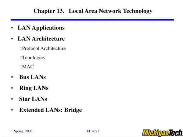
LAN Standards (IEEE802.x) • Advantages of standards • Assure sufficient volume to keep costs down • Enable equipment from various sources to interconnect • IEEE 802 committee developed, revises, and extends standards • Use a three-layer protocol hierarchy: physical, medium access control (MAC), and logical link control (LLC)
IEEE LAN Standards • IEEE 802.2: Logic link control (LLC) layer of data link layer • IEEE 802.3: Ethernet • IEEE 802.4: Token bus, an old protocol • IEEE 802.5: Token ring • IEEE 802.6: Distributed queue dual bus (DQDB) protocol, similar to FDDI • IEEE 802.9: Integrated voice and data networking, including ISDN, Iso-ethernet • IEEE 802.11: Wireless LAN • IEEE 802.12: 100Base-VG • IEEE 802.13: 100Base-X • IEEE 802.14: Cable modem
*Logical Link Control • Specifies method of addressing and controls exchange of data • Independent of topology, medium, and medium access control • Unacknowledged connectionless service (higher layers handle error/flow control, or simple apps) • Connection-mode service (devices without higher-level software) • Acknowledged connectionless service (no prior connection necessary)
Provides a means of controlling access to a shared medium Two techniques in wide use CSMA/CD Token passing LLC frames data, passes it to MAC which frames it again MAC control (e.g. priority level) Destination physical address Source physical address *Medium Access Control
Ethernet (IEEE 802.3) The Ethernet LAN standard was originally developed by DEC, Xerox, and Intel, but has since become a formalized standard by the Institute of Electrical and Electronics Engineers as IEEE 802.3
Ethernet Topology Ethernet uses a bus topology (a high speed circuit and a limited distance between the computers, such as within one building). From the outside, an ethernet LAN appears to be a star, because all cables connect to the central hub. Most ethernet LANs span sufficient distance to require several hubs, but some ethernet LANs are build without the use of hubs (coax bus).
Ethernet Media Access Control Carrier Sense Multiple Access with Collision Detection (CSMA/CD) • Wait until the bus is free and then transmit. • If no collision, transmission is completed. • If the collision is detected, send a jamming signal. • Wait a random amount of time, then re-broadcast.
Token Ring (IEEE 802.5) Token Ring was originally developed by IBM, and have since been standardized by IEEE as IEEE 802.5.
Token Ring Media Access Control • Token ring uses a controlled-access technique called token passing. • The “token” is a series of bits, travels between the computers in a predetermined sequence. • A computer with a message waits to transmit until it receives a free token. The computer changes the free token to a busy token and attaches its message to it. Then it retransmits it on the circuit to the next computer in the sequence. • The computer receiving the message, changes the acknowledgement to ACK (or NAK) and sends the message back to the sender, who creates a new free token.
Token Ring Media Access Control Token loss: • The token crashes before being transmitted - lost a free token • A computer in the ring crashes - lost a busy token • A token is always busy. A solution for the “lost” token problem: • Designate one computer to be the token monitor and another computer to be a backup token monitor. • If no token circulated through the network for a certain length of time or if a busy token circulates too often, the token monitor will create a new free token (and destroy the busy token if necessary.)
Backbone Network Devices Physical Data Link Network Device Operates at Messages Layer Layer Layer Hub Physical All transferred S/D Same Same Bridge Data link Filtered using S/D Same Same data link layer add. Switch Data link Switched using S/D Same Same data link layer add. Router Network Routed using S/D S/D Same network layer add. Gateway Network Routed using S/D S/D S/D network layer add.
Hubs • The active central element of the star layout. • When a single station transmits, the hub repeats the signal on the outgoing line to each station. • Physically a star; logically a bus. • Hubs can be cascaded in a hierarchical configuration.
Hubs Operating at the physical layer, hubs are very simple devices that pass all traffic in both directions between the LAN sections they link. They may connect different types of cable, but use the same data link and network protocol. Strictly speaking, hubs are not considered part of a backbone network, but are usually repeaters or amplifiers.
Bridges • Allow connections between LANs and to WANs • Operates at Layer 2 (Data Link Layer) of OSI • Used between networks using identical physical and link layer protocols • Provide a number of advantages • Reliability: Creates self-contained units • Performance: Less contention • Security: Not all data broadcast to all users • Geography: Allows long-distance links
Bridge Functions • Read all frames from each network • Accept frames from sender on one network that are addressed to a receiver on the other network • Retransmit frames from sender using MAC protocol for receiver • Must have some routing information stored in order to know which frames to pass
Bridges If a bridge receives a packet with a destination address that is not in the address table, it forwards the packet to all networks or network segments except the one on which it was received. Bridges are a combination of both hardware and software, typically a “black box” that sits between the two networks, but can also be a computer with two NICs and special software.
Ethernet Hubs and Switches • Shared medium hubs • Switched LAN hubs x
Switches Like bridges, switches operate at the data link layer. Switches connect two or more computers or network segments that use the same data link and network protocol. They may connect the same or different types of cable.
Switches Switches operate at the same layers as bridges but differ from them in two ways: • First, most switches enable all ports to be in use simultaneously, making them faster than bridges. • Second, unlike bridges, switches don’t learn addresses, and need to have addresses defined. Example: Intel Express 510 T switch.
Switched Ethernet • A simple concept behind switched Ethernet - replace the LAN hub with a switch. Each computer now has its own dedicated point-to-point circuit. • By increasing the number of connections from the server to the switch, the throughput of the server will be improved because of more circuits.
Types of Switches • Store and forward switch • Accepts a frame on input line • Buffers it briefly • Routes it to appropriate output line • Cut-through switch • Begins repeating the frame as soon as it recognizes the destination MAC address • Higher throughput, increased chance of error
Routers Routers operate at the network layer. Routers connect two or more LANs that use the same or different data link protocols, but the same network protocol. Routers may be “black boxes,” computers with several NICs, or special network modules in computers. In general they perform more processing on each message than bridges and therefore operate more slowly.
Routers vs Bridges • Routers can choose the best route. • Routers also only process messages specifically addressed to it. • Routers can connect networks using different data link layer protocols. Therefore, routers are able to change data link layer packets. • Routers may split a message into several smaller messages for transmission.
Layer 3 Switches • Problems With Layer 2 Switches • Broadcast overload because of the single MAC broadcast address (e.g. using ARP for Data Link Layer address resolution) • Lack of multiple links - only one path • Normally, the above problems can be solved with several subnets connected by routers. However, • A MAC broadcast frame is then limited to only the devices and switches contained in a single subnet. • A router does all IP-level processing, some of which could be not necessary. • It is implemented in software and slow. • Layer 3 switches implement the packet-forwarding logic of the router in hardware.
Gateways Gateways operate at the network layer and use network layer addresses in processing messages. Gateways connect two or more LANs that use the same or different (usually different) data link and network protocols. The may connect the same or different kinds of cable. Gateways process only those messages explicitly addressed to them.