Differential Leveling
Differential Leveling. Mr. Conrado Agm 230. Leveling Operations. The basic function of the tripod level is to provide the operator with a level line of sight in a 360 ° plane. From this line of sight specific elevation of land surfaces can be determined. Differential Leveling.


Differential Leveling
E N D
Presentation Transcript
Differential Leveling Mr. Conrado Agm 230
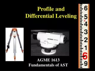
Leveling Operations • The basic function of the tripod level is to provide the operator with a level line of sight in a 360° plane. • From this line of sight specific elevation of land surfaces can be determined.
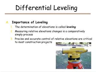
Differential Leveling • The process of determining the difference in elevation between points. • The starting point may be an official bench mark or a point to which an arbitrary elevation has been assigned • Illustration • A typical differential level • Bench mark with a 100.00 foot elevation • Object is to determine elevation of a new point.
Differential Leveling • Procedure • Instrument operator notes that the elevation of the bench mark is 100.00 feet • The instrument operator sets up and levels the instrument a suitable distance away from the BM in direction towards the new point (point A). Sighting distance should not be so great as to make it impossible to accurately read the rod.
Differential Leveling 3. The instrument operator makes a backsight reading of 3.60 feet on the rod which is held plumb on the bench mark by the rodman. After taking the reading the I-O checks instrument level. 4. The reading is entered into his notes in the BS column. To obtain the height of instrument (HI) the BS is added to the bench mark elevation (100.00ft) 103.60 feet is then entered into the HI column.
Differential Leveling • The rodman moves toward point A. He must remember. • Distance readable by instrument • Length of rod • Place rod on solid surface • Be sure front of rod faces instrument • The instrument operator aligns telescope toward rod, focuses, and checks bubble level. He takes a foresight reading of 2.10ft and rechecks level. Entering the reading in his notebook he subtracts 2.10ft from his HI and obtains an elevation of 101.50ft. This is the first rod position which is identified HS turning point. Each student subsequent rod location is also a turning point.
Differential Leveling 7. The rodman stays at TP1 while the IO makes a new set-up in the direction of point A. He then takes a backsight of TP1 to get a new height of instrument.
Differential Leveling 8. Steps 2 through 7 are repeated until point A is reached and its elevation relative to bench mark is obtained. • An experienced field party can make the necessary readings and notes and do the calculations later. It is advised though that beginners do calculations as you go, to be sure no mistakes are made.
Field Notes for Differential Leveling • Field notes for leveling should be kept in five columns. • Station • Backsight • Height of instrument • Front sight • Elevation • Notes (optional)
Field Notes for Differential Leveling • The example shown was modified to assist beginners • Typewritten – readings taken in the field • Handwritten – computations made from the readings • A (+) sign was added to the BS column because BS is added to elevation to find HI. • A (-) sign was added to the FS column because FS is always subtracted from HI to find elevation.
Field Notes for Differential Leveling • Now lets go back to our example and fill in the field notes • Since the first BS is taken at the BM, the reading (3.60) is entered on the BM line – BS column. • The next line is identified with the instrument symbol sub-note 1 to indicate instrument height (103.60) set-up number one.
Field Notes for Differential Leveling • Since the next sight is a foresight on TP1, it is entered on a new line labeled TP1 – column FS (2.10) • When the elevation of TP1 is calculated it is also entered on this same line (101.50) • The next sight after the instrument is moved is a BS taken on TP1 - in the BS column (6.40)
Field Notes for Differential Leveling • Repeat the steps until final point is reached. • It is advisable to use the opposite notebook page to draw a rough map of your route and for remarks for future reference.