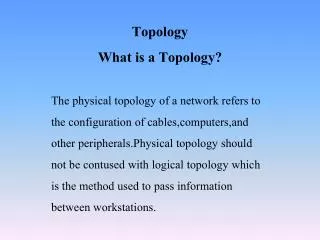
Download
1 / 27
460 likes | 1.02k Views
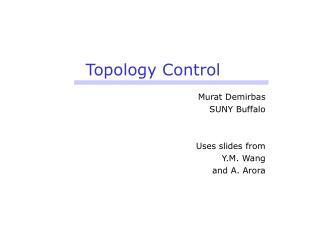
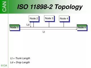
ISO 11898-2 Topology. Ld. Lt. Lt = Trunk Length. Ld = Drop Length. Node 3. Node 2 . Node 4. Node 1. Node n. ISO 11898-2 Network Set-up. node 1 . . . . . . . . node n. CAN_H. CAN Bus Line. 120 . 120 . CAN_L. Electromagnetic Interference. V

E N D
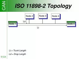
ISO 11898-2 Topology Ld Lt Lt = Trunk Length Ld = Drop Length Node 3 Node 2 Node 4 Node 1 Node n
ISO 11898-2 Network Set-up node 1 . . . . . . . . node n CAN_H CAN Bus Line 120 120 CAN_L
Electromagnetic Interference V Vdiff = const EMI t CAN_H CAN Bus Line 120 120 Vdiff CAN_L
Nominal Bus Level min. 1 µs CAN_H CAN_H + CAN_L CAN_L Dominant Recessive Recessive Voltage 5 V 3.5 V 2.5 V 1.5 V 0 V Time
Broadcast Communication Filter Filter Filter Filter CAN Station 1 (Consumer) CAN Station 2 (Producer) CAN Station 3 (Consumer) CAN Station 4 (Consumer) Local Intelligence Local Intelligence Local Intelligence Local Intelligence Frame I bus lines
Remote Request Frame I Filter Filter Filter RTR I Filter CAN Station 1 (Requester) CAN Station 2 (Producer) CAN Station 3 (Consumer) CAN Station 4 (Consumer) Local Intelligence Local Intelligence Local Intelligence Local Intelligence bus lines
Multiple Bus Access Frame I Filter Frame 3 Filter Filter Frame 2 Filter CAN Station 1 CAN Station 2 CAN Station 3 CAN Station 4 Local Intelligence Local Intelligence Local Intelligence Local Intelligence bus lines
CAN Data Frame Bus Idle IFS CRC Field ACK Field EOF S O F Arbitration Field Control Field Data Field 1Bit 7 Bit 3 Bit 0 to 8 Byte 16 Bit 2 Bit 12 or 32 Bit 6 Bit Remark: CAN Specification 2.0 B passive implementations can’t store or transmit Extended Data Frames; CAN Specification 2.0 B active implementations can store and transmit Standard Data Frames as well as Extended Data Frames.
CAN Remote Frame Bus Idle S O F Arbitration Field Control Field Inter- Mission CRC Field ACK Field EOF 1 Bit 7 Bit 3 Bit 16 Bit 2 Bit 12 or 32 Bit 6 Bit • CAN controller with receive buffer or receive FIFOs answers Remote Frames only under CPU control. • CAN Controller with standard message storing answers Remote Frame automatically without CPU control. • CAN Controller with advanced message storing answers Remote Frames automatically and optionally under CPU control.
Arbitration Field Base Frame Format Arbitration Field Control Field Data Field SOF 11 bit Identifier RTR IDE r0 DLC Extended Frame Format Arbitration Field Control Field SOF 11 bit Identifier SRR IDE 18 bit Identifier RTR r1 r0 DLC Trade-off: longer bus latency time (20 bit-times) longer frames (20 bit-times plus stuff-bits) reduced CRC performance
Bus Arbitration Method ID 100 Data ID 20 Data ID 80 ID 80 Data ID 100 Data ID 20 Data ID 80 Data Frame transmission request Node 1 Node 2 Node 3 Bus
Collision Avoidance Listening Mode Listening Mode Data DLC Listening Mode S R O Identifier T Control Data F 10 9 8 7 6 5 4 3 2 1 0 R Field Field Node 1 (Tx) Node 2 (Tx) Node 3 (Tx) Node 4 (Tx) recessive Bus (4 x Rx) dominant
Communication Services Producer Consumer(s) Write Object indication(s) request 0 to 8 Byte CAN Data Frame Read Object indication request(s) CAN Remote Frame response confirmation(s) 0 to 8 Byte CAN Data Frame
Data-rate/Bus-length Ratio u u u u u u u u [Mbit/s] 1.6 1.0 0.9 0.8 0.7 0.6 0.5 0.4 0.3 0.2 0.1 [km] 0.1 0.2 0.3 0.4 0.5 0.6 0.7 0.8 0.9 1.0 1.1 1.2
Practical Bus Length Nominal Bit-Time 1 µs 1.25 µs 2 µs 4 µs 8 µs 20 µs 50 µs 100 µs Bus Length 30 m 50 m 100 m 250 m 500 m 1000 m 2500 m 5000 m Bit Rate 1 Mbit/s 800 kbit/s 500 kbit/s 250 kbit/s 125 kbit/s 62.5 kbit/s 20 kbit/s 10 kbit/s
ISO11898-2 Parameter • DC Parameter • Length-Related Resistance (r): • 70 m /m • Termination Resistor (Rt): • nominal 120 (min. 108 , max. 132 ) • AC Parameter • Impedance (Z): • nominal 120 (min. 108 , max. 132 ) • Specific Line Delay: • 5 ns/m
DC Characteristics Bus Length Termination Resistance Bus Cable Max. Baudrate Length- Related Resistance Bus-Line Cross-Section 0.25 mm2 .. 0.34 mm2 AWG23, AWG22 124 (1%) 1 Mbit/s at 40 m 70 m/m 0 .. 40 m <60 m/m 0.34 mm2 .. 0.6 mm2 AWG22, AWG20 127 (1%) 500 Kbit/s at 100 m 40 .. 300 m <40 m/m 0.5 mm2 .. 0.6 mm2 AWG20 150 to 300 100 Kbit/s at 500 m 300 .. 600 m 600 m .. 1 km <26 m/m 0.75 mm2 .. 0.8 mm2 AWG 18 150 to 300 50 Kbit/s at 1k m
Cable Drop Length Rules of thumb for the maximum length of a unterminated cable drop Ld and for for the cumulative drop length Ldi: n Ld < tPROPSEG / ( 50 * tP ) Ldi < tPROPSEG / ( 10 * tP ) i=1 tPROPSEG : length of the propagation segment of the bit period tP : specific line delay per length unit Example: bit rate = 500 kbit/s: tPROPSEG = 12 * 125ns = 1500 ns; tP = 5 ns/m n Ld < 1500 ns/ (50 * 5 ns/m) = 6 m; Ldi < 1500 ns/(10 * 5 ns/m) = 30 m i=1
CiA DS-102 Pin Assignment 9-pin D-Sub: DIN 41652 Pin Signal Description 1 - Reserved 2 CAN_L CAN_L bus line dominant low 3 CAN_GND CAN Ground 4 - Reserved 5 (CAN_SHLD) Optional CAN Shield 6 GND Optional Ground 7 CAN_H CAN_H bus line dominant high 8 - Reserved 9 (CAN_V+) Optional CAN external supply
CAN node sales figures 355 2003 273 2002 2001 203 120 2000 57 1999 1998 31 32-bit µC 2,60 10,10 40,50 45,07 75,60 16-bit µC 18,77 59,20 102,10 141,50 171,80 8-bit µC 25,70 37,07 45,47 71,95 92,48 stand-alone 10,70 14,45 15,20 15,30 15,70 in million units total 57,77 120,82 203,27 273,82 355,58 2000 sales by regions: Europe: 85% America: 9% Asia: 6% Application
CAN Reference Model Layers Implementation CAN-based Profiles Software Software CAN-based Application Layer CAN Data Link Layer CAN Controller CAN Physical Layer Transceiver
CAN standardization CiA Application Profiles Application Profile SAE J1939 -based Application Profiles ODVA Device Profiles CiA Device Profiles Device Profile SDS EN 50325-3 DeviceNet EN 50325-2 CANopen EN 50325-4 Application Layer ISO 11898-1 (29-bit ID) Data Link Layer CAN 2.0A ISO 11898-1 (11-bit ID) ISO 11898-1 (11-bit ID) ISO 11898-1 (11-bit and 29-bit ID) ISO 11898-2 Physical Layer RS-485 ISO 11898-2 ISO 11898-2
CAN History Milestones • 1982: Start of the Bosch-internal CAN development • 1986: First public presentation of CAN in Detroit at SAE conference • 1987: First CAN controller chip from Intel • 1990: Introduction of CAN Kingdom protocols • 1992: Foundation of CiA international users and manufacturers group • 1993: Publishing of ISO 11898 (CAN standard) • 1993: Introduction of CAN Application Layer (CAL) • 1993: Introduction of SAE J1939 application profile • 1994: 1st international CAN Conference in Mainz • 1994: Introduction of DeviceNet • 1994: Smart Distributed System (SDS) • 1994: Introduction of CANopen profile family • 1995: Foundation of ODVA • 2000: Foundation of CAN Kingdom International • 2001: Introduction of Time-triggered CAN (TTCAN) protocol • 2002: DeviceNet, SDS, and CANopen become European standards (EN50235) • 2003: ISO 11898-1 and ISO 11898-2 are published
CiA Operations Structure * temporarily inactive Progr. Devices Safety Maritime Medical Truck Gateway Railways Municipal vehicles Weaving Machine Lift Control Electronic Door Passenger Info IEC 61131-3 CANopen Special Interest Groups * * * * TF Extruder down- stream TF Battery Generic I/O Drive Virtual Terminal Closed- Loop * * * * TF Road construct- ion ASAM Encoder Off-road Vehicles Hydraulics Business Committee Managing Director Technical Committee approves and manages elects approves and manages GENERAL ASSEMBLY * CAL Interest Groups CANopen approves and manages CANopen Benelux Marketing Groups Russia USA
CiA Services • CANschool (technical training for newcomers) • CANopen seminar (technical training) • In-house seminars ( customer-specific training) • CANopen product guide (free-of-charge) • Quarterly CAN Newsletter (free-of-charge) • Review of proprietary CANopen profiles • CANopen device certification • CAN literature and specification sales