Overview of PXL Sensors and Their Development for High Energy Physics Applications
300 likes | 434 Views
This document provides a comprehensive overview of PXL sensors, including their size, pixel specifications, integration times, power dissipation, and readout mechanisms. Key features include efficient binary output, remote threshold adjustments, and radiation hardness, with research showing over 95% efficiency for MIPs. The evolution of these sensors, from initial prototypes to the current generation and planned next steps, is discussed. This includes testing results and specifics about sensor interfaces, configurations, and architecture tailored for high-energy physics at IPHC.

Overview of PXL Sensors and Their Development for High Energy Physics Applications
E N D
Presentation Transcript
Sensor Requirements Sensor requirements (consistent with IPHC development direction) • ~2 cm x 2 cm (1 reticle) size. • Pixel size < 30 µm. • Integration time of ≤ 200 µs for L = 8 x 1027 cm-2s-1 • Power dissipation ≤ 170 mW/cm2 (air cooling) • Binary output with remote threshold adjustment • Efficiency of ≥ 95% for MIPs with a simultaneous accidental noise rate of ≤ 10-4 • Maintain efficiency and accidental rate after radiation exposure of 90 kRad and 1012 1 MeV neq / cm2. • ≤ 4 LVDS output channels (ladder space) • Remote configuration
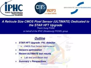
Talk Outline • MAPS @ IPHC • Principle of operation • Readout speed and integration time • Radiation hardness • PXL sensors development path • Current generation of sensors • Characteristics • Testing results • Next generation of sensors • Sensor interface • High resistivity substrate
MAPS @ IPHC • Principle of operation • Readout speed and integration time • Radiation hardness • PXL sensors development path • Current generation of sensors • Characteristics • Testing results • Next generation of sensors • Sensor interfaces • High resistivity substrate
MAPS @ Institut Pluridisciplinaire Hubert Curien • IPHC-DRS (former IRES/LEPSI) proposed using MAPS for high energy physics in 1999 • CMOS & ILC group today • 6 physists • 9 microcircuit designers • 6 test engineers • 7 PhD students CNRS - IPHC, Strasbourg-Cronenbourg • More than 30 prototypes developed • several pixel sizes and architectures (simple 3-transistor cells, pixels with in-pixel amplifiers and CDS processing) • different readout strategies (sensors operated in current and voltage mode, analog and digital output) • Large variety of prototype sizes (from several hundreds of pixels up to 1M pixel prototype with full-reticule size) MIMOSA (Minimum Ionizing particle MOS Active sensor)
Monolithic Active Pixel Sensors MAPS pixel cross-section (not to scale) • Standard commercial CMOS technology • Room temperature operation • Sensor and signal processing are integrated in the same silicon wafer • Signal is created in the low-doped epitaxial layer (typically ~10-15 μm) → MIP signal is limited to <1000 electrons • Charge collection is mainly through thermal diffusion (~100 ns), reflective boundaries at p-well and substrate → cluster size is about ~10 pixels (20-30 μm pitch) • 100% fill-factor • Fast readout • Proven thinning to 50 micron
Charge Sharing and Cluster Size MimoSTAR2 test results (30 μm pixel pitch) Based on tests of several different prototypes S/N>12 allows detection efficiency >99.6%
MAPS Integration Time = Readout Time • Typical sensor readout • Raster scan • Charge integration time = array readout time • Multiplexed sub-arrays to decrease integration time • Column parallel readout architecture • All columns readout in parallel and then multiplexed to one output • Charge integration time = column readout time
From Analog to Binary Readout Analog readout – simpler architecture but slower readout Digital readout – offers increased speed but requires on-chip discriminators or ADCs and increased S/N for on-chip signal processing
MAPS @ IPHC • Principle of operation • Readout speed and integration time • Radiation hardness • PXL sensors development path • Current generation of sensors • Characteristics • Testing results • Next generation of sensors • Sensor interfaces • High resistivity substrate
PXL Sensors Development Path ADC CDS Data sparsification readout to DAQ Pixel Sensors CDS Disc. Complementary detector readout digital signals analog signals digital analog MimoSTAR sensors 4 ms integration time 1 2 Phase-1 sensors 640 μs integration time 3 PXL final sensors (Ultimate) < 200 μs integration time Sensor and RDO Development Path
Current Generation of Sensors • Phase-1 prototype • Architecture based on Mimosa22 • AMS-C35B4/OPTO which uses 4 metal- and 2 poly- layers • 14 μm epitaxial layer • Reticle size (~ 4 cm²) • Pixel pitch 30 μm • ~ 410 k pixels • Column parallel readout • Column discriminators • Binary readout of all pixels • Data multiplexed onto 4 LVDS outputs @ 160 MHz • Integration time 640 μs • Functionality tests and yield look very good. • Measured ENC is 15 e-. • Beam test to measure MIP efficiency planned for 2010. • Phase-2 prototype • Small mask adjustments to improve discriminator threshold dispersion
Phase1/2 Testing Results 55Fe calibrations: noise ~14 e─ counts ADC counts • Discriminator transfer functions: • Phase-1 • FPN 0.6 mV to 1 mV • temporal noise 1-1.2 mV • Phase-2 • FPN ~0.5 mV • temporal noise ~0.9 mV 1 0 Row # Column # Threshold (mV)
Phase 1 vs. Phase 2 Our test results feed back to IPHC designs to improve sensor performance Phase-1 chip B6 Phase-2 chip A2 In Phase-2 the magnitude of discriminator threshold variations is smaller than in Phase-1.
Next Generation PXL Sensor Zero suppression circuitry (SUZE) • Design based on Mimosa26 architecture • Reticle size (~ 4 cm²) • Pixel pitch 20.7 μm (recent change) • 890 k pixels • Reduced power dissipation • Vdd: 3.0 V • Optimized pixel pitch vs. Non-ionising radiation tolerance • Estimated power consumption ~134 mW/cm² • Short integration time 185.6 μs • Improved pixel architecture • Optimized discriminator timing • Improved threshold uniformity • on-chip zero suppression • 2 LVDS data outputs @ 160 MHz
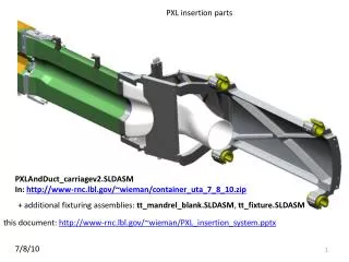
Phase1 and Final PXL Sensor Interface Required “ladder” interface Required testing interface
MAPS @ IPHC • Principle of operation • Readout speed and integration time • Radiation hardness • PXL sensors development path • Current generation of sensors • Characteristics • Testing results • Next generation of sensors • Sensor interfaces • High resistivity substrate
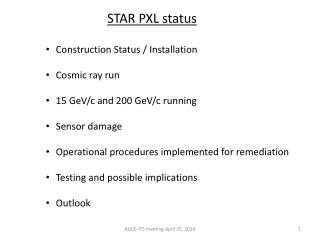
Sensor performance satisfies requirements Sensors design at IPHC is on schedule High resistivity substrate dramatically improves S/N and removes radiation hardness issues The design of the final PXL sensor will benefit from the ongoing tests of Mimosa22HR and latch up tests of Mimosa22HR and memory prototypes planned later this year Phase-2 will be used for ladder prototyping We will build a 3-sector detector prototype equipped with Phase-2 sensors to test it at STAR (2012) Summary
Phase1/2 testing results The Phase-1 performance tested on several chips1 demonstrated FPN ranging from 0.6 mV to 1 mV and temporal noise estimated at 1-1.2 mV.
MAPS principle of operation Classical diode with reset read Reset noise, offset Continuous reverse bias (self-biased) No reset noise, no offset read
Sensor/RDO Requirements by generation Gen Sensor Sensor RDO Mimostar–2 30 µm pixel, 128 x 128 array 1.7 ms integration time 1 analog output Mimostar–3 30 µm pixel, 320 x 640 array 2.0 ms integration time 2 analog outputs Phase–1/2 30 µm pixel, 640 x 640 array 640 µs integration time, CDS 4 binary digital outputs Final (Ultimate) 18.4 µm pixel, 1024 x 1088 array ≤ 200 µs integration time, CDS, zero suppression 2 digital outputs (addresses) 50 MHz readout clock JTAG interface, control infrastructure ADCs, FPGA CDS & cluster finding zero suppression ≤ 4 sensor simultaneous readout 160 MHz readout clock JTAG interface, control infrastructure zero suppression 120 sensor simultaneous readout 160 MHz readout clock JTAG interface, control infrastructure 400 sensor simultaneous readout (full system) 1 DONE 1 2 PROTOTYPED 3