Introduction to SolidWorks
Introduction to SolidWorks. Select File. Part Modeling. Select File New Part (already selected – highlighted blue ). Sketcher Layout. Select Sketch and choose Sketch (2D). Start Sketching. Sketch tools. Part manager, keeps track of all your work (modeling). Principal planes.

Introduction to SolidWorks
E N D
Presentation Transcript
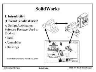
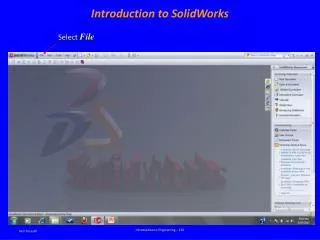
Introduction to SolidWorks Select File Introduction to Engineering – E10
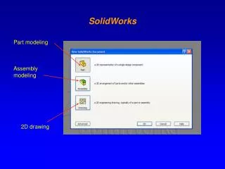
Part Modeling Select File New Part (already selected – highlighted blue) Introduction to Engineering – E10
Sketcher Layout Introduction to Engineering – E10
Select Sketch and choose Sketch (2D) Introduction to Engineering – E10
Start Sketching Sketch tools Part manager, keeps track of all your work (modeling) Principal planes Introduction to Engineering – E10
Sketching Tangent Draw using the sketch tools Feedback from sketcher, vertical and horizontal Origin (0,0) Midpoint Make sure the new line snaps to the end of the previous line (indicated by the large circle). Do not guess the location Introduction to Engineering – E10
Assigning Units To assign units, select Tools and then Options Select Document Properties, Units andchoose the Unit system desired Introduction to Engineering – E10
Dimensioning To dimension, select Smart Dimension, click on the line, drag to a desired location, click again and enter value To edit dimension, double click the value and enter the new value Introduction to Engineering – E10
Making a Solid from the Sketch Exit sketch Right click for other option like dimensioning Introduction to Engineering – E10
Features Select Features Introduction to Engineering – E10
Extrusion, select Blind and assign a thickness Select thickness Introduction to Engineering – E10
Hollowing out as you Extrude Thickness Thin feature in Extrusion Introduction to Engineering – E10
Revolve, select axis of rotation and amount of rotation Select a line to revolve about Select the Revolve option Introduction to Engineering – E10
To make a hole at the top, select Sketch, select top surface and draw a circle Introduction to Engineering – E10
Select Extruded Cut option Introduction to Engineering – E10
Features Fillet (round edges) Feature Menu Pattern (circular and linear Applied features, no need for a sketch Solid making commands, a two dimensional sketch is needed Extrude – create (unite or join) Sweep – create (unite or join) Extrude – cut (subtract) Sweep – cut (subtract) Revolve– create (unite or join) Loft (sweep and blend)– create (unite or join) Revolve – cut (subtract) Loft (sweep and blend – cut (subtract) Introduction to Engineering – E10
Display Menu Displays the previous view Zooms the model to fit the screen Display style Shaded view with edges shown Zooms to a specified area by opening a window Shaded view Scrolls the view, Pan Solid not shaded Solid with hidden lines shown Wireframe To rotate the model on the screen: hold the middle mouse button down and move the mouse Introduction to Engineering – E10