SolidWorks
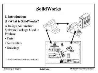
SolidWorks. 1. Introduction (1) What is SolidWorks? A Design Automation Software Package Used to Produce Parts Assemblies Drawings. (From Planchard and Planchard 2003). (2) Starting Up Window: Start->Programs->SolidWorks 2007-> SolidWorks 2007. (3) References Online Help

SolidWorks
E N D
Presentation Transcript
SolidWorks • 1. Introduction • (1) What is SolidWorks? • A Design Automation Software Package Used to Produce • Parts • Assemblies • Drawings (From Planchard and Planchard 2003)
(2) Starting Up Window:Start->Programs->SolidWorks 2007-> SolidWorks 2007
(3) References • Online Help • Menu: Help->SolidWorks Help Topics • Online Tutorial • Menu: Help->SolidWorks Tutorial • Books: • D. C. Planchard and M. P. Planchard, SolidWorks 2007: The Basics, SDC Publications, 2007 • D. C. Planchard and M. P. Planchard, Engineering Design with SolidWorks 2007, SDC Publications, 2007 • D. C. Planchard and M. P. Planchard, Engineering Design with SolidWorks 2003, SDC Publications, 2003
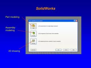
(4) SolidWorks Model Types e.g., Base.sldprt Base-Rod.sldasm Base.slddrw
2. Part Modeling (1) Setting Up Unit Menu: Tools->Options
– Hole + Block Top Plane (2) 3-D Object Creation Procedure By Creating Features • Each Feature: • 2-D Sketching • 3-D Formation
(3) 2-D Sketching • Parametric Modeling • (a) Procedure • Sketch the geometry • Dimension the geometry • Modify the dimension values • e.g., 0.42 1.43 1 1 0.35 1 1.51 1
(b) 2-D Object Creation Methods Menu: Tools->Sketch Entities 3 Point Arc Line Tangent Arc Centerpoint Arc Point Rectangle Spline Circle
(c) Additional 2-D Object Creation Methods Menu: Tools->Sketch Tools Chamfer Fillet Mirror Trim Offset Entities Extend
Angular Radial Linear (d) DimensioningMenu: Tools->Dimensions->Smart (e) RelationsMenu: Tools->Relations Collinear Perpendicular Vertical Horizontal
Midpoint Coincident Tangent Parallel Equal Coradial Concentric Symmetric
(4) Features Menu: Insert->Boss/Bass Extruded Boss/Base Revolved Boss/Base Menu: Insert->Cut Revolved Cut Extruded Cut
Menu: Insert->Boss/Bass Sweep Boss/Base Lofted Boss/Base Menu: Insert->Features Fillet Chamfer
Menu: Insert->Pattern/Mirror Linear Pattern Circular Pattern Mirror
Z Y X (5) Reference Geometry Menu: Insert->Reference Geometry Axis Coordinate System Plane e.g., A reference plane for creating a sketch of revolved cut feature
(6) Viewing Menu: View->Display Hidden Lines Removed Shaded With Edges Hidden Lines Visible Wireframe Menu: View->Modify Rotate Pan Zoom to Fit
3. Assembly Modeling • Loading the Components • Menu: Insert->Component • ->Existing Part/Assembly
(2) Defining Mates Menu: Insert->Mate
(3) Exploded View Menu: Insert->Exploded View
4. Drawing Modeling 2-D Drawing of a Part or an Assembly (From Planchard and Planchard 2003)
(1) Drawing Template and Drawing Format • Orientation • Landscape • Portrait • Size • A • B • A4 • A3 • ... ... (From Planchard and Planchard 2003) Menu: File->New->Draw
(2) Creating Views • Menu: Insert->Drawing View • Standard 3 View Top View Right View Front View
Model View Model View Orientation
Derived Drawing Views Projected View Auxiliary View Detail View Crop View Broken-Out Section Section View
(3) Dimensions Menu: Tools->Options Select Styles of Font, Leader, Precision, Tolerance, Arrow, etc. Two Ways to Create Dimensions (i) Display All Dimensions and Then Modify These Dimensions Menu: Insert->Model Items (ii) Create Required Dimensions Manually Menu: Tools->Dimensions
(4) Annotations Menu: Insert->Annotations 1 3 x 25 ABC Datum Feature Symbol Balloon Note Surface Finish Symbol Geometric Tolerance Center Mark
(5) Bill of Materials Menu: Insert->Tables->Bill of Materials