Download
1 / 169
1.74k likes | 2.2k Views
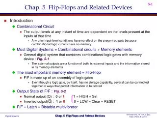
Flip-Flops and Related Devices. Chapter 8. S-R (SET-RESET) Latch. Active-HIGH input Active-LOW input S-R Latch S’-R’ Latch. S-R (SET-RESET) Latch. S-R Latch Logic Symbol. Switch Contact De-bounce. Figure 8--6 . When the set is high and reset is low Q is high and Q’ is low.

E N D
Flip-Flops and Related Devices Chapter 8
S-R (SET-RESET) Latch Active-HIGH input Active-LOW input S-R Latch S’-R’ Latch
When the set is high and reset is low Q is high and Q’ is low
Once set ie Q high, then with S and R both low nothing change.
With reset high and set low the flip=flop give a Q’ high and a Q low.
The state of both set and rest high is not allowed since it would give a illogical condition.
S-R flip flop truth table for NOR flip-flop S R Q Q’ 0 0 Q Q’ hold condition 1 0 1 0 set 0 1 0 1 reset 1 1 0 0 not allowed
S-R flip flop using NANDs Set high reset low Q high Q’ low
Both set and reset high is not allowed but give both Q and Q’ as high
S-R flip flop truth table for NAND flip-flop S R Q Q’ 0 0 Q Q’ hold condition 1 0 1 0 set 0 1 0 1 reset 1 1 1 1 not allowed
S-R flip flops do not come ready made but a 7402 dual 2input NOR came be used to make the S-R flip flops
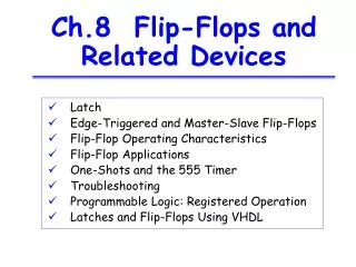
Gated SR Latch • A gate input is added to the S-R flip-flop to make the flip-flop synchronous. • In order for the set and reset inputs to change the flip-flop, the gate input must be active (high). • When the gate input is low, the flip-flop remains in the hold condition.
When the gate is high The flip flop works
Truth Table for S-R gated Flip Flop S R G Q Q’ 0 0 0 Q Q’ Hold 1 0 0 Q Q’ Hold 0 1 0 Q Q’ Hold 1 1 0 Q Q’ hold 0 0 1 Q Q’ hold 1 0 1 1 0 set 0 1 1 0 1 reset 1 1 1 0 0 not allowed
Gated D Latch • The D (data) flip-flop has a single input that is used to set and to reset the flip-flop. • When the gate is high, the Q output will follow the D input. • When the gate is low, the flip-flop is latched.
The J-K flip-flop has a toggle mode of operation when both J and K inputs are high.Toggle means that the Q output will change states on each active clock edge. J, K and Cp are all synchronous inputs. The master-slave flip-flop is constructed with two latches. The master latch is loaded with the condition of the J-K inputs while the clock is high. When the clock goes low, the slave takes on the state of the master and the master is latched. The master-slave is a level-triggered device. The master-slave can interpret unwanted signals on the J-K inputs.
I would love to show this circuit Toggle but it will not since the Mater S-R flip flop is seeing a not allowed 1 1 input and putting out a 0 at Q and Q’ both.
But This Will Toggle 1 2 3
Truth Table for J-K Flip Flop J K Q 0 0 Q Hold 1 0 1 Set 0 1 0 Reset 1 1 Q’ Toggle
The edge-triggered J-K will only accept the J and K inputs during the active edge of the clock. The small triangle on the clock input indicates that the device is edge-triggered. A bubble on the clock input indicates that the device responds to the negative edge. no bubble would indicate a positive edge-triggered device.
J and K are both high, this means a toggle at the negative edge of the clock
Toggle Toggle Remain the same Reset Reset
Flip-Flop Operating Characteristics • Propagation Delay Times • Set-up Time • Hold Time • Maximum Clock Frequency • Pulse Width • Power Dissipation
Propagation Delay • Clk to Output Q • Preset’ and CLR’ to Output Q
Setup Time and Hold Time • Setup Time • Hold Time
Flip-Flop Applications • Parallel Data Storage • Frequency Division • Counting
A race condition occurs when the data inputs (J-K or D) to a flip-flop are changing at the same time as the active clock transition. The top J-K Flip Flop should not work due to a race condition The bottom J-K flip flop should work
Top Flip Flop Top Clock Bottom Flip Flop Bottom delayed clock
Set-up time is the time that the data inputs to a flip-flop must be set before the active clock transition. 20ns of set up time is required for the J-K flip flop to accept the high at K
Hold time is the amount of time that the data inputs must maintain their level after active clock transition. The clock in blue is after the active K in red the flip flop will not work