Download
1 / 18
260 likes | 841 Views
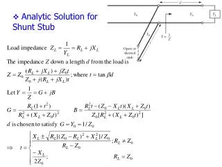
Analytic Solution for Shunt Stub. Problem 1 : Repeat example 5.5 using analytic solution. Example5.6: Design two single-stub (open circuit) series tuning networks to match this load Z L = 100 + j 80 to a 50 line, at a frequency of 2 GHz?. Solution.

E N D
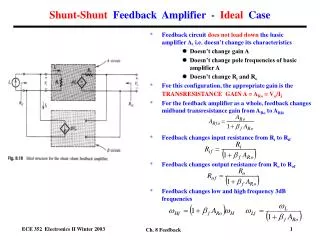
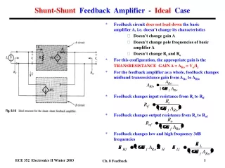
Example5.6: Design two single-stub (open circuit) series tuning networks to match this load ZL= 100+j 80 to a 50 line, at a frequency of 2 GHz? Solution 1. The normalized load impedance ZL= 2-j1.6. 2. SWR circle intersects the 1+jx circle at both points z1 = 1.0-j1.33 z2 = 1.0+j1.33. Reading WTG can obtain: d1= 0.328-0.208=0.12 d2= 0.672-0.208=0.463. 3. The stub length for tuning z1 to 1 requires l1 = 0.397, and for tuning z1 to 1 needs l2 = 0.103.
1. ZL= 100+j 80 at 2 GHz can find R= 100,L=6.37nH.
Double-Stub Matching adjustable tuning • Variable length of length d between load and stub to have adjustable tuning between load and the first stub. • Shunt stubs are easier to implement in practice than series stubs. • In practice, stub spacing is chosen as /8 or 3/8 and far away 0 or /2 to reduce frequency sensitive. • Original circuit • Equivalent circuit
Disadvantage is the double-stub tuner cannot match all load impedances. The shaded region forms a forbidden range of load admittances. • Two possible solutions b1,b2 and b1’,b2’ with the same distance d.
Example5.7: Design a double-stub (open circuit) shunt tuning networks to match this load ZL= 60-j 80 to a 50 line, at a frequency of 2 GHz? Solution 1. The normalized load impedance YL= 0.3+j0.4 (ZL= 1.2-j1.6). 2. Rotating /8 toward the load (WTL) to construct 1+jb circle can find two values of first stub b1 = 1.314 b’1 = -0.114. 3. Rotating /8 toward the generator (WTG) can obtain y2= 1-j3.38 y’2= 1+j1.38.
4. The susceptance of the second stubs should be b2 = 3.38 b’2 = -1.38. 5. The lengyh of the open-circuited stubs are found as l1 = 0.146, l2 = 0.204, or l1 = 0.482, l2 = 0.350. 6.ZL= 60-j 80 at 2 GHz can find R= 60, C=0.995pF.
Quarter-Wave transformer • It can only match a real load impedance. • The length l= /4 at design frequency f0. • The important characteristics
Example5.8: Design a quarter-wave matching transformer to match a 10 load to a 50 line? Determine the percent bandwidth for SWR1.5? Solution
Binomial Multi-section Matching • The passband response of a binomial matching transformer is optimum to have as flat as possible near the design frequency, and is known as maximally flat. • The important characteristics
Binomial Transformer Design • If ZL<Z0, the results should be reversed with Z1 starting at the end.
Example5.9: Design a three-section binomial transformer to match a 50 load to a 100 line? and calculate the bandwidth for m=0.05? Solution
Using table design for N=3 and ZL/Z0=2(reverse) can find coefficient as 1.8337, 1.4142, and 1.0907.