Download
1 / 16
160 likes | 185 Views
This presentation reviews the circuit design of the analog section of the Board Game Counter, including the block diagram, combinational logic section, and sequential logic section. It explains how the Analog Section produces a dampened square wave to increment a binary count and encodes it into the die’s seven dots. The session also discusses the simplified and actual versions of the analog section, with detailed timing analysis. Explore this demo to deepen your understanding of board game counter electronics.

E N D
Board Game Counter Demo - Analog • This presentation will • Review the Board Game Counter block diagram. • Review the circuit design of the analog section of the Board Game Counter. 2
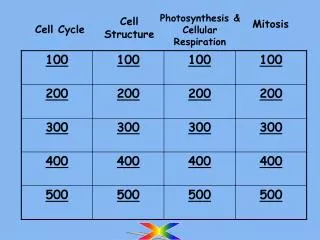
Board Game Counter Block Diagram Combinational Logic Section L1 L2 L3 L4 L5 L6 L7 Analog Section Sequential Logic Section A B C CLOCK The Analog Section produces a dampened square wave that “rolls” the count and slowly stops. On every pulse of the clock, the Sequential Logic Section increments a binary count from 1 to 6, then repeats. The Combinational Logic Section encodes the binary count into the die’s seven dots.
Board Game Counter Block Diagram Combinational Logic Section L1 L2 L3 L4 L5 L6 L7 Analog Section Sequential Logic Section A B C CLOCK The Analog Section produces a dampened square wave that “rolls” the count and slowly stops. On every pulse of the clock, the Sequential Logic Section increments a binary count from 1 to 6, then repeats. The Combinational Logic Section encodes the binary count into the die’s seven dots.
Analog Section Schematic Diagram CLOCK
A Simplified Version • When the push button switch is pressed, the 100uf capacitor (C1) will quickly charge to 5 volts through the 1.2 k resistor (R8). • As long as the push button switch remains pressed, top end of the 10 k resistor (R9) will be held at 5volts. This results in a simplified version that is equivalent to a standard 555 time oscillator. Actual Version Simplified Version
Analysis of Simplified Version Period: A RA RB Frequency: C
Simulation of Simplified Version VOUT VC
Simplified Version – Timing Analysis Period: VOUT VC Frequency:
The Actual Version • When the push button switch is pressed and held, the actual analog section of the Board Game Counter performs like a standard 555 time oscillator. However, for the Board Game Counter to operate correctly, the oscillation must slow and eventually stop. • This is where the 100uf capacitor (C1) and the 1.2 k resistor (R8) play a role. Actual Version Simplified Version
Simulation of Actual Version Push Button Pressed Push Button Released VOUT VC VLimit
Actual Version – Timing Analysis • When the push button is pressed, the 555 Timer produces a 66 Hz square wave. • Once the push button is released, the frequency gradually decreases (period increases). • Eventually the oscillation will stop. Push Button Pressed Push Button Released VOUT VC VLimit B A C
Timing Analysis at Time A A Period: Frequency:
Timing Analysis at Time B B Period: Frequency:
Timing Analysis at Time C C Period: Frequency:
Board Game Counter – Analog Sequential Logic Section Combinational Logic Section Analog Section Discussed in a future lesson