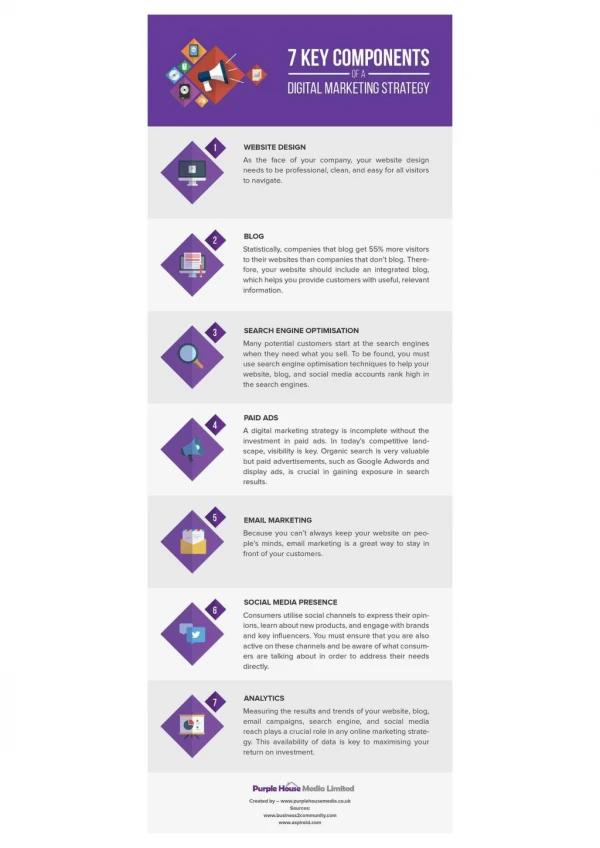
System Components & Installation
NFS2 - 3030. System Components & Installation. RFX. SLC L3 ~ L10. RDP Up to 32. SLC L2: Det.159 Mod. 159. 4 Set On Board Relay O/P. SLC L1: Det.159 Mod. 159. EIA 485. Noti-Fire-Net. EIA 232. Onyxworks. J7 SLC. J1 NUP. J6 SCTY. J2 LCD. J5 TROUBLE. J4 BACKLIGHT. J13

System Components & Installation
E N D
Presentation Transcript
NFS2 - 3030 System Components & Installation
RFX SLC L3 ~ L10 RDP Up to 32 SLC L2: Det.159 Mod. 159 4 Set On Board Relay O/P SLC L1: Det.159 Mod. 159 EIA 485 Noti-Fire-Net EIA 232 Onyxworks
J7 SLC J1 NUP J6 SCTY J2 LCD J5 TROUBLE J4 BACKLIGHT J13 AMPS-24 J9 KEYPAD TB4 TB3 TB2 TB1 ALARMTROUBLE SUPVSCTY TB7 ACS TB9 RDP TB5 PRN TB6 +24V
Function Keys Display & Function Keys Function LEDs
LEM CONNECTION SLC WIRING TO NEXT LCM FROM CPU J7 or LCM
TB1 B+ A+ B- A- SLC JP2 J3 +5V D33 JP1 J1 D32 EG FAULT D28 SW1 JP3 J2 Loop Modules LEM Ground Fault LCM Ground Fault LCM-320 LEM-320
LCM/LEMSLC Connector Typical Style 6.0/7.0 Typical Style 4.0 Channel B Channel A Channel A Return Channel B Output
AMPS-24(E) Power Supply TB6 Accessory Power TB2 CPU TB1 SLC TB3 AC SW1 Configuration Switches TB4 & 5 DC SW4 Charger Selection
AMPS-24E (New Version) AC Input: AC 220V DC Output: 24VDC, 5A for CPU 24VDC, 3A for External Devices Battery Charger: 24VDC 7 – 200AH
APS2-6RE– Auxiliary Power Supply AC Input: AC 220V DC Output: 24VDC, 3A (2 set) 24VDC, 6A (1 set) (Total 24VDC, 6A)
Addressable Charger Power Supply ACPS 610(E) AC Input: AC 220V DC Output: 24VDC, 1.25A x 4 Circuits Battery Charger: 24VDC 7 – 200AH
TB2 24v Power From AMPS-24 From APS-6R Max 10 ohms TB1 RDP Bus 12 to 18 AWG Max 4K feet total Max 100 ohms SW17 #1 ON: Prog #2 ON: ELR LCD-160 Remote Display 160 character display Custom graphics Tactile keypad DCC participation
A1P1 A1P2 A1P3 A1P4 ACS Annunciators ACM (AEM) – 48 A ACM(AEM)-24AT
1 2 3 4 5 6 7 8 0 0 9 9 1 1 8 8 2 2 3 7 7 3 6 4 4 6 5 5 ACS Annunciators LDM-32 series ACM-8R
All Auto Manual Acknowledge Switch Group 1 Switch Group 2 Switch Group 3 Switch Group 4 Switch Group 5 Switch Group 6 Switch Group 7 Switch Group 8 ACS Annunciators SCS-8 Smoke Control Station
Control On Control Off Monitor On Monitor Off SCS-8 Smoke Control Station • Up to four modules/group • Three position toggle switches • On / Off / Auto
Network Communications Module To communicate with another Onyx control panel on a network, the Onyx Panels requires an Network Control Module. The NCM is capable of working on a either a wire or a fiber network. • NCM-W (Wire) • NCM-F (Fiber optic) Mounting Options: • In a standard Chassis position. • On the right side of a DAA Audio Amplifier. • Underneath the DVC Digital Video Controller. NCM-W
A B A B A B A B Network Node Network Node or RPT Network Node or RPT Network Node Point-To-Point Configuration • A point-to-point wiring configuration is defined as a twisted-pair segment with only two nodes/repeaters attached to it. Terminating resistors are required at each end of every segment, and are built into each MIB/RPT/NCM.
A B A B A B A B Network Node or RPT Network Node or RPT Network Node or RPT Network Node or RPT Point-To-Point Configuration • Wiring a Noti-Fire-Net in NFPA Style 7 point-to-point.
CPU-3030D or CPU-3030ND • Both CPU options require a CHS-M3 chassis for mounting in the top position of the cabinet. CPU2 mounting AMPS-24(E) LCM/LEM and NCM-W/F can be installed in the two right-hand positions. BATTERY SBB-D4 D-Size Backbox
CHS-4L • CHS-4L Chassis, low profile, 4 positions for mounting the LCM/LEM, NCM-W/F, APS-6R, LDM-32, BACNet GW... D-Size Backbox
Dress Panels & Plates DP-1B Blank Dress Plate, 4 row DP-DISP Display Dress Plate ADP-4B Annunciator Dress Plate* BP2-4 Battery Dress Plate *Use to BMP-1 Blank Module plate to cover unused single positions
Page 19 DR-A4 SBB-A4 The assembly consists of a back box and a locking door with two keys. The back box and door can be ordered separately or as a complete unit. Doors may be hinged right or left. A semi-flush trim ring kit is available for each box size.
Page 19 DR-B4 SBB-B4
Page 20 DR-C4 SBB-C4
Page 20 DR-D4 SBB-D4
ABS-2D ABS-4D