Download
1 / 12
150 likes | 443 Views
FE analysis with shell and axisymmetric elements E. Tarallo, G. Mastinu POLITECNICO DI MILANO, Dipartimento di Meccanica. Summary. Subjects covered in this tutorial An introduction to shell elements in out-of-plane loading problem

E N D
FE analysis with shell and axisymmetric elements E. Tarallo, G. Mastinu POLITECNICO DI MILANO, Dipartimento di Meccanica
Summary • Subjects covered in this tutorial • An introduction to shell elements in out-of-plane loading problem • An introduction to axisymmetric elements in axial loading problem • Formulations and problems of shell and axisymmetric elements • A guided example to evaluate a simple structure through the use of FEM • Comparison between analytical and numerical solution • Other few exercises (to include in exercises-book)
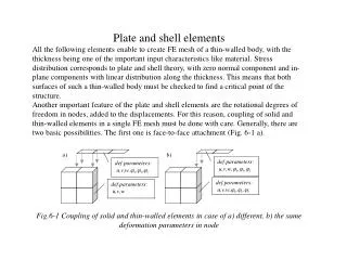
Shell element – topic • Use shell elements to model structures in which one dimension (the thickness) is significantly smaller than the other dimensions and in which the stresses in the thickness direction are negligible. (thickness less than 1/10 of global structural dimension). • Hp: plane sections perpendicular to the plane of the shell remain plan. • Define shell: thickness, direction of the normal, number of layers, stiffness calculation method, reference surface • Problem – curvature: with a coarse mesh Abaqus may determine several independent surface normals at the same node for adjoining elements. • Thin (a) or Thick (b)? From CAE: • for thin: S4R5, S8R5, STRI65, S9R5. • for thick: S3/S3R, S4/S4R, S8R.
Shell element – guidelines • The linear, finite-membrane-strain, fully integrated, quadrilateral shell element (S4) can be used when greater solution accuracy is desired (problems prone to membrane- or bending-mode hourglassing, or in-plane bending problems). • The linear, finite-membrane-strain, reduced-integration, quadrilateral shell element (S4R) is robust and is suitable for a wide range of applications. • The linear, finite-membrane-strain, triangular shell elements (S3/S3R) can be used as general-purpose elements (refine mesh to capture bending deformations or high strain gradients because of the constant strain approximation). • To account for the influence of shear flexibility, use the shell elements suitable for modeling thick shells (S4, S4R, S3/S3R, S8R); check that the assumption of plane sections remaining plane is satisfied. • Quadratic shell elements, either quadrilateral or triangular, are very effective for general, small-strain, thin-shell applications. These elements are not susceptible to shear or membrane locking. • If you must use second-order elements in contact simulations, do not use the quadratic, triangular shell element (STRI65). Use the 9-node, quadrilateral shell element (S9R5) instead. • For very large models that will experience only geometrically linear behavior, the linear, thin-shell element (S4R5) will generally be more cost-effective than the general-purpose shell elements.
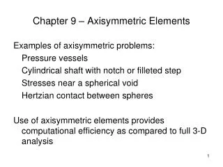
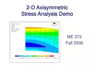
Axisymmetric element – topic • Axisymmetric elements provide for the modeling of bodies of revolution under axially symmetric loading conditions. A body of revolution is generated by revolving a plane cross-section about an axis (the symmetry axis) and is readily described in cylindrical coordinates. • Abaqus does not apply boundary conditions automatically to nodes that are located on the symmetry axis in axisymmetric models. If required, you should apply them directly. • In Abaqus/CAE it’s only available torsionlessaxisymmetric element where the state of stress and strain is univocally defined by the deformation in r-z plane.
Exercise 1 - shell Part: 3D shell planar Material: E=210 GPa, ν=0.3 Thickness: 5 or 50 mm Load: 100 Mpa (pressure) Boundary: constrained translation (only on midplane) Problem: Perform static analysis with shell (2 thicknesses) Find max displacement and max von S11 stress Perform static analysis with solid (2 thicknesses) Compare the results btw shell and solid
Exercise 2 - axisymmetric Material: E=210 GPa, ν=0.3 Internal pressure: p=100 Mpa Boundary: use Ysym condition Analysis: Static Problem:compare analytical solution with numerical solution S11: S33:
Exercise 3 Material: E=210 GPa, ν=0.3 Internal pressure: p=4 Mpa Boundary: encastre Moment: 10 Nm Analysis: Static Problem:compare shell model with the equivalent solid model
Exercise 4 - axisymmetric A rotating disk with a hole Material: E=210 GPa, ν=0.3 Load: rotation 1000 rpm Analysis: Static Problem: compare stress analytical solution vs numerical solution