Download
1 / 43
430 likes | 581 Views
PCCUK DECT Troubleshooting Seminar – 22 nd Aug 2006. Objectives: - Review DECT Communication. - Review correct installation procedure. - Understand Site Survey requirements. - Understand CS positioning requirements. - Verifying an installation;

E N D
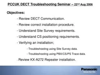
PCCUK DECT Troubleshooting Seminar – 22nd Aug 2006 Objectives: - Review DECT Communication. - Review correct installation procedure. - Understand Site Survey requirements. - Understand CS positioning requirements. - Verifying an installation; - Troubleshooting using Site Survey data. - Troubleshooting using PBX/CS/PS Trace data. - Review KX-A272 Repeater installation.
DECT Communication Review: Relevant TDA Equipment RF Specification CODEC (ADPCM) DECT Frame Structure Cell Station Handover
Relevant TDA DECT Equipment: KX-TDA15/30/100/200/600 PBX Systems Cell Stations (CS) - KX-TDA0142CE (TDA100/200/600) – Via CSIF Card – Max 4 calls/CS • - KX-TDA0141CE (TDA15/30/100/200/600) – Via DHLC/DLC Card – Max 2 calls/CS Cell Station Interface Cards (CSIF) - KX-TDA0143 CSIF4 - One CSIF4 card supports 4 CS • - KX-TDA0144 CSIF8 – One CSIF8 card support 8 CS • NB: When installing CSIF in a TDA600/620 system, aim to mount all CSIF cards within the same shelf. DECT Portable Stations (PS) - KX-TCA155/255/256 • - KX-TD7590/7580 DECT Repeater (Range Extender) - KX-A272
Adaptive Differential Pulse Code Modulation ADPCM sample Typical PCM samples @ 8bits and 8000 samples/second giving a bit rate of 64Kbits/s. ADPCM only encodes the ‘difference’ between each sample, as these steps are comparatively small, samples are @ 4 bits rather than 8, giving a bit rate of 32Kbits/s. PCM sample
DECT Frequency Structure DECT Frequency Structure Carrier Channels
DECT Frame Structure DECT Multiplex And Frame Structure 384 4 Parity Voice/User Data
Available channel restrictions KX-TDA0142 (Illustration). • 4 Voice Channels + 2 Data channels • Channels are limited by available Timeslots (max 12). • 2 Timeslots are needed to sync antenna (1 R.F. unit per CS)
Available channels KX-TDA0158 8-ch CS (Illustration). • 8 Voice Channels + 4 Data channels • All available Timeslots (max 12) can be utilized. • 1 Timeslot is needed to sync antenna (2 R.F. units per CS)
Call Set-Up Optimal Channel selected through RSSI Channel selected and communication request transmitted Communication link established Channels scanned for communication requests NB: PS Antenna symbol will be shown if sufficient RSS to select channel from PS. The Antenna symbol does not indicate sufficient RSS to establish a call through CS.
Channel Selection Channel 1 Poor Signal Channel 1 Poor Signal Channel 1 Channel 2 Channel 2
Cell – Cell Handover Cell 1 Cell 2 Channel 1 Channel 2 Channel 1 Channel 2 Direction of Handset Movement
Signal Interference Multi-Path Fading Reflected Wave Reflected Wave Reflecting Surface Cell StationAntenna Diversity Cell Station Antenna Diversity counters rapid interference of Signal Level (fading)
DECT System Installation Considerations: Golden Rules: • Site the CS so that it will be free of dust and moisture and will remain in the 0 ~ 40 degree C range. • Do not place the CS in direct sunlight, outdoors, near high-voltage equipment or any other equipment capable of producing high ‘noise’ levels. • Do not place the CS on, or near, a metal object. • Do not use this DECT system near other wireless systems. • Do not place too many CS within a small area, aim to separate each CS by 25 ~ 40m. (Both Horizontal and Vertical separation.) This distance will vary depending on the environment and can be determined by Site Survey. • NB: Where more than 4 voice channels are required in a given area, it is possible to place a maximum of 2 CS within a confined area (Level < 11). • However, never place more than 2 CS within a confined area (Level < 11), to do so will cause handover and call-drop problems.
DECT System Installation Considerations: • Environmental Considerations :- To prevent devices from interfering with each other, do not place devices closer together than the distances mentioned below:-
DECT System Installation Procedure Overview: • IMPORTANT: • The Site Planning / Site Survey is the most critical part of the installation process. • It is not acceptable to install a Panasonic DECT System without following the correct procedure. • It is not acceptable to assume that a Panasonic CS can be placed in the same position as previous/competitors CS. Each CS type has different coverage properties. • An incorrectly / poorly conducted Site Survey WILL result in poor area coverage, frequent noise, out-of-range warnings and call-drop. • For reliable results, use only a TCA255 for Site Survey. (FYI-604)
DECT System Installation Procedure: A) Site Planning: • Obtain a site-map/floor-plan of the proposed CS installation site. • Confirm that the customers expectations are understood and can be met. • Identify the service area (and number of call paths if > 4) required by the user on the map. • Plan the location of each CS, taking local environmental conditions into consideration. • The following slides show examples of both poor and useful site-maps:-
Site-Map: Example of a poor Site-Map. • This Site-Map does not provide accurate distance information, or environmental data.
Site-Map: Example 1 of a useful Site-Map. • Good Points :- • The Handover area can be seen on one page. • The distance between each CS can be seen accurately (and can be found via grid) • Information for all floors are contained in one file.
DECT System Installation Procedure: B) Site Survey preparation: • Check and assign the CS ID number to the PS (KX-TCA255). • Assign a channel number to each CS by setting the DIP switches appropriatly on the rear of the CS. • Install a temporary CS (using a battery box if necessary) in the planned position. NB: Install the CS > 2m above the floor. Please refer to the TDA Installation manual for further details.
DECT System Installation Procedure: C) Conduct the Site Survey: • Test the RSS Level using the PS (KX-TCA255), ensure that the RSS Level near the CS is Level 12. • Walk away from the CS and monitor the change in the RSS Level. • Mark on the Site-Plan, the areas which have RSS Level “8” and Level “3”. • Move the CS’s until adjacent CS’s overlap by 5m (with RSS Level between “8” and “10”) • Ensure no more than 2 CS’s overlap with RSS Level > “10” • Ensure that the RSS Level is > “3” at any location in the service area. • The following slide shows a good site survey :-
Site-Survey: Example of a good Site-Survey. CS3 CS2 • CS Positions and RSS Level can be easily seen (Colours, numbers etc) • CS Overlap area is easy to see • This Site Survey shows an installation problem – what is it?
DECT System Installation Procedure: D) Complete the Installation: • Ensure all DIP switches no the CS’s are set to “Off”.. • Connect the CS’S to the PBX, placing them at the positions indicated on the site-plan. • Register the PS’s to the PBX and make a test call while walking around the service area. • If noise or disconnection occurs, study the area where the problem happened and either :- • Relocate the CS’s in that area • Add an additional CS • Ensure that the installation complies with the “Golden Rules”. • After all problems have been resolved, mount the CS permanently.
DECT System Installation Procedure (Multi-Floor Environment)-1: E Stairwell F C D B A • Caution: Great care must be taken when installing DECT systems in multi-floor environments. • Floor 2 • Floor 1 • = Walking Direction • = CS Coverage area • Why is the above not a good installation, what problem could occur ?
DECT System Installation Procedure (Multi-Floor Environment)-2: • Answer: When the user walks from Floor 1 to Floor 2, CS handover occurs until the user approaches the CS D in the Floor 1 stairwell. At this point, out-of-range tone is heard, as the user continues up the stairwell, the call is dropped. • Reason: CS B on Floor 1is within range of CS C on Floor 2. The PS has performed handover between CS B and CS C. As CS C is not within range of CS D, the call will fail. • Solution: Move CS C so it is out of range of CS B, preventing the problem handover. • NB: This example is taken from an actual field problem site.
Troubleshooting using Trace data: There are three possible types of trace data which can be taken to aid DECT Troubleshooting; • TDA PBX Trace data (as per S-H 78) – not described in this presentation. • KX-TCA255/256 PS Trace data (as per S-H 81) • KX-TDA0142/141 CSTrace data The above data can be taken simultaneously (providing sufficient PC’s exist) and provides useful additional data for Design team analysis. It is not possible to directly read the trace data, it needs to be forwarded to Design team for analysis
Obtaining KX-TDA255/256 CSTrace data - 1 The TCA255/256 can be used to take trace data for analysing such problems as Hand-over, noise etc (NB: Special trace s/w is required in PS) The trace is taken directly from the PS while roaming between CS’s. i. Configure HyperTerminal Requirements: • KX-TCA255 V1.08 • Or • KX-TCA256 • TCA255 Trace cable (not download cable) • PC + HyperTerminal • Baud Rate: 19200 • Data: 8 Bits • Parity: None • Stop Bit: 1 Bit • Flow Ctrl: None
Obtaining KX-TDA255/256 CSTrace data - 2 Check the ‘Echo typed …’ box Check the ‘Wrap lines …’ box ii. Configure the Terminal Settings
Obtaining KX-TDA255/256 CSTrace data - 3 iii. Connect the PS to the PC using the special trace cable. Click the ‘Call’ Tab
Obtaining KX-TDA255/256 CSTrace data - 4 iv. Start the ‘Capture Text’ function – specify a meaningful file name.
Obtaining KX-TDA255/256 CSTrace data - 5 v. Access the PBX PHONE BOOK menu on the PS, then enter the following commands via HyperTerminal :- trc 15 <cr> ok trc 17 <cr> ok trc 32 <cr> ok trc 34 <cr> ok trc 38 <cr> ok trc 39 <cr> ok NB: Commands must be input within 30s or PS will lockup. Remove the PS battery to recover.
Obtaining KX-TDA255/256 CSTrace data - 6 CS 1-4-4 CS 1-8-3 CS 1-6-7 vi. Make a call from the PS to a PT while standing under the 1st CS, wait 2mins and proceed to the next CS etc. NB: Check that the route walked and the CS shelf-slot-port numbers are marked on the site-map etc vii. Stop the Text Capture and save the file. viii. Send the Trace data (and site-map, site-survey data and DSYS file to PCCUK for analysis.
Obtaining KX-TDA0142/141 CSTrace data - 1 • A. Set-up the following HyperTerminal profile on your PC :- • Baud Rate: 19200 • Data: 8 bits • Parity: None • Stop Bit: 1 bit • Flow Ctrl: None
Obtaining KX-TDA0142/141 CSTrace data - 2 Check the ‘Send line ends …’ box. • B. Configure the Terminal Settings :- Check the ‘Wrap lines …’ box.
Obtaining KX-TDA0142/141 CSTrace data - 3 • Connect the ‘special’ cable to the PC and the CS (remove the cover) • Press CTRL+’D’ on the PC to start the Debugger s/w on the CS III. Start the ‘Capture’ function To begin the trace, type; CS>trf s7 1f 23 28 2e CS>mts Make test calls etc CS>mte Stop the ‘Capture’ function, send the data to PCCUK for analysis.
DECT Repeater Installation (KX-A272)-1 • The KX-A272 repeater extends the range of a DECT system into areas which previously gave poor reception. • No additional cabling is required for it’s installation. • The same ‘Golden rules’ apply as per a KX-TDA0141/142 installation, however it should be noted that a maximum of 6 repeaters can be registered to a CS. It is also possible to verify the coverage area of a DECT Repeater by utilising the following repeater features :- • Site Survey Mode - as per a CS, the RSS in the intended operational area of the repeater can be verified before final placement – make sure to add this data to the overall Site Survey Map. • Verification tone– this feature allows a tone to be superimposed on any DECT communication which passes through the repeater. This can be used to check that the PS is in range of the repeater.
DECT Repeater Installation (KX-A272)-2 • Important notes: A. DECT Repeater + KX-TDA0142/141 – Noisy environment. • Where interference is experienced on DECT communication path (White noise, other electrical noise etc), consider installing a DECT Repeater in the problem area. • The antenna/BBIC design is different between a KX-A272 Repeater and a KX-TDA0141/142. • This differing antenna/BBIC design can make the repeater less susceptible to external electrical interference than the existing CS’s Refer to the case study on slide 2a ~ 2c:- • The KX-TDA0158 (8ch CS – planned launch 2007) will incorporate a different antenna/BBIC design to existing CS. • This ‘new’ CS may provide some countermeasure for noisy environments.
DECT Repeater Installation (KX-A272)- Noisy Environment – 2a • When performing a site survey, it is important to note not just the RSSI Level, but also the Error Count. • The following shows typical error counts and their effects :- KX-TCA255 Display (SS) The following values are important :- > 0~50 / 9999 – minor noise present > 50~100 / 9999– noise evident > 100 /9999 – severe noise evident Radio Strength CH0 SLOT:06 SYNC L:12 0000 0100 CS-ID:9005301234 - RSSI - Error count - Measure count NB: If a high error count is detected, it is the responsibility of the dealer to explain to the end user that this may cause noise in their system
DECT Repeater Installation (KX-A272)- Noisy Environment – 2b The following picture shows an actual example of a noisy installation:- There is a high error count as there is much DECT signal reflection caused by the surroundings :- i.e. walls and ceilings are metal, there is nothing to absorb stray reflected signals The following slide shows how the DECT performance can be improved :-
DECT Repeater Installation (KX-A272)- Noisy Environment – 2c • The DECT performance may be improved by installing DECT Repeaters, and moving the CS out of the problem area :- CS CS A272 A272 - High error count
DECT Repeater Installation (KX-A272)-3 • Important notes: B. DECT Repeater + PS Ring Group • There are 4 communication slots available to a DECT Repeater, each speech path occupies 2 slot. • When a PS Ring Group call is made, one slot is used for calling the PS Ring Group. • Problem: If there are 2 PS (in the same Ring Group) in the area of the repeater – 1 PS will ring, but cannot answer the call. • Solution: Do not use PS Ring Groups where it is possible to have 2 PS in the repeater’s coverage area. • Or, • Add additional CS’s and Repeater’s to increase the number of available communication slots. NB: The above is true for PT to PS call, PS to PS call is not affected, as a communication slot is not occupied in this case.
DECT Repeater Installation (KX-A272)-4 • Important notes: C. DECT Repeater + KX-TDA0141 CS • When a KX-TDA0141 is used in an installation, it’s CS ID is assigned dynamically by the PBX. • The Repeater uses this CS ID to register itself to the CS, but this ID can change if the PBX is powered on/off. • Problem: If a repeater is within range of 2 or more TDA0141 CS and the PBX is powered off/on, the Repeater may register to a different TDA0141 CS, affecting the coverage area. • Solution: Install DECT Repeater / TDA0141 combinations carefully. Try to avoid installations using many DECT Repeaters + TDA0141’s. NB: The KX-TDA0142 CS ID is a static ID, and does not change even after PBX power off/on, hence this consideration is specific to KX-TDA0141 CS.
Demonstrations: • A. Site Survey using TCA255 • B. Collecting PBX Trace data • C. Collecting CS Trace data • D. Collecting PS Trace data • Questions: • Thanks for your attention.