Download
1 / 14
160 likes | 313 Views
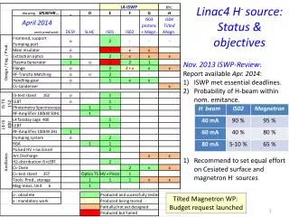
Linac4 H 2 injection system. P. Carrié , F. Fayet , R. Guida , S. Izquierdo Rosas , J. Rochez, A. Wasem, M. Wilhelmsson J. Lettry, R. Scrivens , E. Mahner. Roberto Guida PH-DT-DI. Linac4 Ion Source Review November 14th , 2013. Outlook. Introduction

E N D
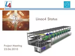
Linac4H2injection system P. Carrié, F. Fayet, R. Guida, S. Izquierdo Rosas, J. Rochez, A. Wasem, M. Wilhelmsson J. Lettry, R. Scrivens, E. Mahner Roberto Guida PH-DT-DI Linac4 Ion Source Review November 14th, 2013
Outlook • Introduction • H2 supply systems: description • Software Controls and User Interface • Performances • Budget analysis • Conclusions Outlook Roberto Guida PH-DT-DI
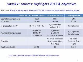
Linac4 H2 supply system • Two identical systems: 3 MeV Test Stand and Bldg400: • Each system contains H2 gas supply for Ion Source and LEBT • H2 supply at 3 MeV Test Stand operational since August 2012 • H2 supply at Linac4 Bldg400 operational since August 2013 LEBT Ion Source Introduction Roberto Guida PH-DT-DI
The team involved PH-DT-DI/GasService….. Patrick Carrié, Roberto Guida, Albin Wasem EN-MEF………………… FabriceFayet, Mats Wilhelmsson EN-ICE…………………. Silvia M. Izquierdo Rosas, Jacques Rochez Linac4…………………… Jacques, Richard, Edgar, Michael Introduction Roberto Guida PH-DT-DI
Ion Source H2 supply Ion Source temperature for H2 density regulation MFM mass-flow meters: Monitoring H2 flow Monitoring of primary supply and line pressure XMPC: pressure controllers Two for redundancy H2 supply systems Independent P sensors for monitoring/alarms Pump unit for better P regulation and working point below Patm N2 purge Roberto Guida PH-DT-DI
LEBT H2supply MFM mass-flow meters: Monitoring H2 flow XMPC: pressure controllers Two for redundancy Monitoring of primarysupply and line pressure H2 supply systems Independent P sensors for monitoring/alarms N2 purge Pump unit for better P regulation and working point belowPatm Roberto Guida PH-DT-DI
Software controls • Remote monitoring and control • Application running on PLC with remote interface in PVSS • Local touch screen is available • Alarms propagated via email/sms • Prepared following the standard used for gas systems at LHC experiments Operational States Stop – (maintenance, modifications)–all the actuators in their fail-safe positions. H2 has been evacuated from the system. Stand-by – (allows interventions on other systems) –The gas system is stopped with all the actuators in their fail-safe positions, H2 has not been evacuated. Evacuate – (improve gas purity at H2 filling) – H2 is evacuated from the gas system until a certain pressure threshold is reached. Run – (normal gas system operational state): The gas system is running and all the parameters are stable and within the defined limits for this operational state. Controls and Interface Roberto Guida PH-DT-DI
Software controls - Interface User interface Controls and Interface Roberto Guida PH-DT-DI
Software controls - Interface • On-line values and immediate access to one year data • Values published on DIP for other users (i.e. Linac4 control system) Controls and Interface Roberto Guida PH-DT-DI
Software controls - Interface Controls and Interface Roberto Guida PH-DT-DI
Controls and Performances • Safety and Alarms: • Detection of abnormal consumption: • At supply level pressure drop in H2 cylinder • At P regulation level H2 flowmonitoring • Several alarms implemented for system stop, unstable regulation, failure of components, measurements out of range, … • Performances: • Stable operation (the system at the 3 MeV Test Stand is operational since one year) • Gas density regulation is better than 0.5 mbar at 25 °C • System tested with Pressure set-point for operation from 100 mbara to 1800 mbara • About 15 minutes for achieving set-point with standard regulation from vacuum to 1300 mbara (room for improvement) System performances Roberto Guida PH-DT-DI
Performances – gas density regulation Pressure regulation for the Ion Source H2 supply System performances Temperature piezo-valve H2 supply flow measured by MFM Roberto Guida PH-DT-DI
Budget analysis Budget for construction About 55 kCHF(includingmanpower) per rack Roberto Guida PH-DT-DI
Conclusions • Two H2(or other gases) supply racks have been built for 3 MeV Test Stand and final Linac4 system at Bldg400 • Each rack contains fully independent H2supplies for Ion Source and LEBT • Fundamental to study/record the stability of the 4 systems over the coming months/year • Construction based on experience from gas systems for the LHC experiments which demonstrated extremely high availability (>99.9% power cuts excluded) over the last years • Spare parts, maintenance, manpower, … needed for operation to be reviewed in few months • Each system has already an on-site redundancy to cope with unexpected failures Conclusions Roberto Guida PH-DT-DI