Download
1 / 58
580 likes | 608 Views
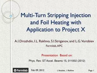
Explore modern injection and extraction methods in accelerator facilities, including 1-turn and multi-turn injection, H- charge exchange injection, and resonant & continuous injection. Learn about envelope matching, fast extraction, kickers & septa, and novel extraction schemes such as crystal extraction. Discover the intricate procedures of beam transfer and beam delivery for efficient particle acceleration.

E N D
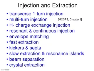
Injection and Extraction • transverse 1-turn injection • multi-turn injection • H- charge exchange injection • resonant & continuous injection • envelope matching • fast extraction • kickers & septa • slow extraction & resonance islands • beam separation • crystal extraction [MCCPB, Chapter 9]
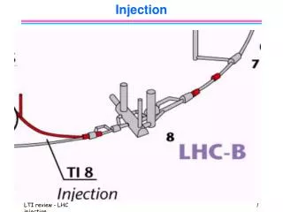
LHC SPS 7/27 of LHC 1/11 of SPS 1/4 of PS The LHC injector chain LINAC PSB PS SPS LHC • Each proton has to pass four circular machines
beam transfer between accelerators • beam removal and beam delivery injection: minimum beam loss minimum emittance dilution 1-turn injection or multi-turn injection for accumulation new or more exotic techniques to control and improve beam properties extraction: reverse process, usually at higher beam energy space-charge effects less important hardware more challenging extraction efficiency(minimize activation and maximum performance) procedure depends on application: fast 1-turn extraction, slow extraction “spill” novel extraction schemes (e.g., bent crystals)
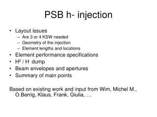
1-turn injection • the beam is brought onto the central orbit using septum magnet and fast kicker magnet arrangement rms closed-orbit variation rms beam sizes momentum error septum thickness
injected beam must at the center of the aperture when it reaches the kicker determines the correlation between xsep and x’sep needed at the exit of the septum can be adjusted by changing the strength of the septum; slope of beam at the kicker is
to position the injected beam on the design orbit the kicker must apply the opposite angular deflection a large value of bkic reduces the kicker strength a large value of bsepreduces the relative contribution to qkic which arises from the septum thickness dsep in case of FODO lattice, septum and kicker are best placed downstream of focusing quadrupole, where b is maximum
septum: dc magnet, dc electrostatic wires stray or leakage fields (nonlinear) can affect stored beam; may be reduced by magnetic shielding kicker(s): fast gap between bunches or bunch trains ~50-100 ns time constants 80 kV, 5000 A, 500 G typical numbers ferrites for field containment ceramic chamber with conducting layer on the inside reduces impedance seen by the beam and heating of the ferrite (conducting layer can be much thinner than skin depth)
other injection issues: transient beam loading of rf cavities phase-space matching (Dx,ybx,y, sz/drms,… must be matched to ring optics; in longitudinal phase space possibly bunch rotation, bunch compression, energy compression, etc.
multi-turn injection e.g., convert a current-limited cw beam from injector into a pulsed beam of higher intensity transverse multi-turn injection ramped orbit bump in the vicinity of the septum instead of a kicker - different for e- and protons for e-radiation damping is utilized: inject 1 bunch, reduce bumpafter few turns, bunch shrinks due to damping, increase bump again, inject next bunch into the same rf bucket; similar for e-cooled protons, or stochastically cooled p-bars (but here usually in longitudinal phase space)
for protons or heavy ions:orbit bump is varied slowly, bunches are injected into different regions of phase space; early bunches in the center of the acceptance some emittance dilution is inherent to this scheme; for N-turn injection:
other possibility: two kickers, powered in parallel by the same pulser only second kicker deflects the injected beam; both kickers act on the stored beam advantage: kicker rise and fall times do not need to be smaller than the bunch spacing, but can be of order of the revolution time requirements on the kicker can be further alleviated by a dc orbit bump which brings the stored beam closer to the septum prior to injection
example injection process for PEP-II note PEP-II peculiarity: injected beam is smaller! (Courtesy M. Donald, 2002)
injection with pulsed sextupole magnet (PSM) motivation: less perturbation of stored beam (no dipole [kickers] or quadrupole oscillations [PQM]) H. Takaki et al, 2007 pulsed kickers pulsed sextupole By vs x Df (x’) stored beam K2 injected beam
longitudinal+transverse multi-turn injection as before ramped local orbit bump with varying amplitude but at the same time the injector linac energyis ramped such that at the injection septum the distance to the closed orbit corresponding to the instantaneous linac energy remains constant smaller transverse emittance, increased energy spread injection b oscillation injection b+d oscillation
10 turns after start of purely transverse injection 20 turns after start of combined transverse&longitudinal inject. simulated horizontal phase space for multiturn injection into LEAR; each bunch represented by three ellipses with slightly different momentum deviations, the two vertical lines on the right represent thickness of the septum (Courtesy Ch. Carli, 2002)
improved optics with larger b at e- cooler combined transverse & longitudinal injection purely transverse injection Effective # turns stored in LEAR vs # injected turns
longitudinal multi-turn injection if for e- ring time between injections is shorter than damping time, multiturn transverse injections become difficult solution: longitudinal injection circulating beam is brought close to the septum by ac bump; injected beam has negative energy offset so that DDd equals physical distance xsep between stored and injected beam injected bunches execute slow synchrotron oscillations no b oscillation
double injection into the same rf bucket at LEP here also the stored bunch is offset in energy so that Dx=2DDd time between injections is half a synchrotron period (similarly, one could inject every Ts/4 period) advantage: factor 2 faster radiation damping than in transverse plane possible disadvantage: time between injections constrained by synchrotron frequency
phase-space painting protons or ions many small linac bunches are injected into different spots of the 2-D or 6-D phase space aim: approximately uniform distribution reduced space-charge effects avoid instabilities which blow up e in uncontrolled way simplest case: painting done by synchrotron oscillations injected beam position can also be moved adiabatically examples: horizontal-longitudinal injection in LEAR (above) horizontal-vertical injection at RAL injected phase-space density P and projection p are related by: radial increment between successive bunches: desired p(x) P(r) R: maximum radius at which bunches are injected, Ninj: total no. of injections
combined vertical/horizontal painting at RAL vary vertical steering magnet in injection line, while the guide field in the ring is decreased initially: small x oscillation large y oscillation later: large x oscillation small y oscillation also a vertical or horizontal orbit bump (or both) in the ring could be employed
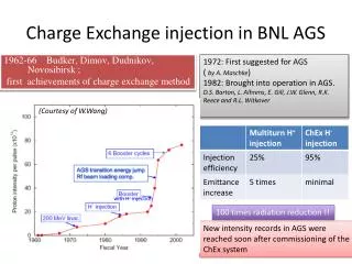
H- exchange injection Novosibirsk 1963 Budker & Dimov H- accelerated by linac stripped to protons when they traverse a thin foil at injection into the ring Liouville’s theorem does not apply, in principle very high phase-space densities possible however, usually painting and uniform distribution preferred to avoid space-charge effects heating limits foil thickness to 50-200 mg cm-2 (<1 mm) stripping efficiency ~98% for 50 MeV protons materials: polyparaxylene, carbon, aluminimum oxide
scattering: Qrms~0.2 mrad for single traversal Qtot ~ N1/2Qrms for N traversals stacking in betatron + synchrotron phase space reduces # traversals schematic of H- injection with stripping foil
following lattice parameters at foil are considered advantageous: transverse acceptance momentum acceptance location between two symmetric focusing quadrupoles unstripped H- beam evelope quadrupole assists in deflecting unstripped H- foil H-
other uses of foils: heavy ions they can be fully stripped (depends on thickness of foil and energy) extracting H0 or p from H- storage ring alternatives: gas jet, laser e- are also stripped in strong magnetic fields
novel H- stripping scheme under study for SNS uses laser&dipoles
other scheme: resonant injection bumper magnets with dipole, quadrupole and octupole fields produce separatrix with two stable islands (sketch) afterwards fields are adjusted so that islands merge opposite process is now studied at the CERN PS for clean extraction “Multi-Turn Extraction”
continuous injection beam continually replenished, beam current constant then average luminosity = peak luminosity steady-state operation for light sources (e.g., SNS) no fill-to-fill variations, no transients quasi-static conditions if at some beam-beam limit tbeam~e-Lconst ? i.e., lifetime decreases exponentially with L gain in peak luminosity
example: PEP-II continuous injection could increase luminosity by factor of 5! each bunch can be replenished every Dt=2.1 s 67-ns bump would move injected bunches to about 4s from stored-beam core for unobstructed passage through the detector minimum supportable lifetime: t~N/DN Dt N: nominal bunch population DN: injected bunch increment Dt: time between injections into same bucket N~1.2x10¹¹, DN~109, Dt~2.1 syields t~4.2min.
injection envelope matching (Michiko) turn-by-turn profiles after injection into the SLC damping ring
D mismatch? before b matching
energy matching two-step strategy: (1) center the closed orbit in the ring by changing the RF frequency (2) center first turn trajectory by adapting the injected beam energy
fast extraction • similar to 1-turn injection • orbit bump move beam close to septum • fast kicker deflects beam into extraction channel • kicker rise time < time separation between successive • bunches or bunch trains • kicker-pulse length & fall time depend on #bunches • to be extracted and fill pattern
minimum deflection angle required kicker just upstream of focusing quadrupole, septum 1 cell downstream, maximum value for b kicker septum m
reduced jitter of extracted beam with double-kicker system (ATF)
kicker & septa kicker: (1) current loop inside vacuum (2) terminated transmission line inside vacuum (3) ferrite magnet outside vacuum (4) multicell transmission lines with ferrite flux returns typical time constants: 50-150 ns (rise and fall times) SLC,NLC: 60 ns PEP-II: 120 ns
fast horizontal kicker with ferrite yokes: t~(lw)/g i.e., ~ length x width/vertical gap shorter time constant by dividing magnet into shorter segments kicker pulsers: thyratron discharges, with filters, capacitors to shape pulses solid-state FET -> potentially shorter time constants
PEP-II kickers kicker magnet cross section pulsing circuit with FET switch
very fast travelling-wave kicker protoype for TESLA: layout
very fast travelling-wave kicker prototype for TESLA: measured output rf pulse 6 ns total pulse length demonstrated deflection angle 24 mrad at 3.3 GeV
N=16 G. Gollin U Illinois Fourier series kicker
septa: small thickness desired • -> weaker kicker, larger extraction • efficiency • electro-static wire septa, e.g., at Tevatron, • 2 354 cm long sections, 75%W255Rh wires • of 0.002 inch diameter and 0.1 inch spacing, • field 83 kV/cm • more widely used: • (b) Lambertson iron septum dipoles • (c) current-carrying septum dipoles • B=m0 J d , if d is small pulsed operation
schematic of Lambertson septum iron magnet c: circulating beam e: extracted beam
cross section of current-sheet septum
slow extraction tune ripple causes uneven spill -> active filters on power supplies, feedforward slow spill can be controlled by tune and chromaticity
conventional multi-turn extraction from CERN PS illustration of conventional scheme for extracting beam from PS to SPS
extraction via resonance islands new “multi-turn extraction” tune variation for proposed resonant extraction