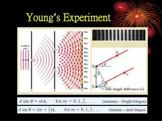
Young ’ s Experiment
Young ’ s Experiment. Coherence. Two sources to produce an interference that is stable over time, if their light has a phase relationship that does not change with time: E ( t )= E 0 cos( w t + f ).

Young ’ s Experiment
E N D
Presentation Transcript
Coherence Two sources to produce an interference that is stable over time, if their light has a phaserelationship that does not change with time: E(t)=E0cos(wt+f) Coherent sources: Phasefmust be well defined and constant. When waves from coherent sources meet, stable interference can occur - laser light (produced by cooperative behavior of atoms) Incoherent sources: fjitters randomly in time, no stable interference occurs - sunlight 35-
Intensity and phase Fig. 35-13 Eq. 35-22 Eq. 35-23 35-
Intensity in Double-Slit Interference E2 E1 35-
Intensity in Double-Slit Interference Fig. 35-12 35-
Ex.11-2 35-2 wavelength 600 nm n2=1.5 and m = 1 → m = 0
Reflection Phase Shifts n1 > n2 n1 < n2 n1 n1 n2 n2 Fig. 35-16 Reflection Reflection Phase Shift Off lower index 0 Off higher index 0.5 wavelength 35-
Phase Difference in Thin-Film Interference Fig. 35-17 • Three effects can contribute to the phase difference between r1 and r2. • Differences in reflection conditions • Difference in path length traveled. • Differences in the media in which the waves travel. One must use the wavelength in each medium (l / n), to calculate the phase. 35-
Equations for Thin-Film Interference ½ wavelength phase difference to difference in reflection of r1 and r2 35-
Color Shifting by Paper Currencies,paints and Morpho Butterflies weak mirror soap film better mirror looking directly down : red or red-yellow tilting :green 35-
Ex.11-3 35-3 Brighted reflected light from a water film thickness 320 nm n2=1.33 m = 0, 1700 nm, infrared m = 1, 567 nm, yellow-green m = 2, 340 nm, ultraviolet
Michelson Interferometer Fig. 35-23 35-
Problem 35-81 In Fig. 35-49, an airtight chamber of length d = 5.0 cm is placed in one of the arms of a Michelson interferometer. (The glass window on each end of the chamber has negligible thickness.) Light of wavelength λ = 500 nm is used. Evacuating the air from the chamber causes a shift of 60 bright fringes. From these data and to six significant figures, find the index of refraction of air at atmospheric pressure. 35-
Solution to Problem 35-81 • φ1the phase difference with air ; 2 :vacuum • N fringes 35-
11-3 Diffraction and the Wave Theory of Light Diffraction Pattern from a single narrow slit. Side or secondary maxima Light Central maximum Fresnel Bright Spot. These patterns cannot be explained using geometrical optics (Ch. 34)! Light Bright spot 36-
The Fresnel Bright Spot (1819) • Newton • corpuscle • Poisson • Fresnel • wave
雙狹縫與單狹縫 • Double-slit diffraction (with interference) • Single-slit diffraction
Diffraction by a Single Slit: Locating the first minimum (first minimum) 36-
(minima-dark fringes) Diffraction by a Single Slit: Locating the Minima (second minimum) 36-
Intensity in Single-Slit Diffraction, Qualitatively 1st side max. N=18 q = 0 q small 1st min. Fig. 36-7 36-
Intensity and path length difference Fig. 36-9 36-
Fig. 36-8 Intensity in Single-Slit Diffraction, Quantitatively Here we will show that the intensity at the screen due to a single slit is: In Eq. 36-5, minima occur when: If we put this into Eq. 36-6 we find: 36-
Diffraction by a Circular Aperture a a Light Light q q Distant point source, e,g., star d Image is not a point, as expected from geometrical optics! Diffraction is responsible for this image pattern q lens 36-
Resolvability Fig. 36-11 Rayleigh’s Criterion: two point sources are barely resolvable if their angular separation θRresults in the central maximum of the diffraction pattern of one source’s image is centered on the first minimum of the diffraction pattern of the other source’s image. 36-
Ex.11-8 36-3 pointillism D = 2.0 mm d = 1.5 mm
Ex.11-9 36-4 d = 32 mm f = 24 cm λ= 550 nm
The telescopes on some commercial and military surveillance satellites Resolution of 85 cm and 10 cm respectively • l= 550 × 10–9 m. • (a) L = 400 × 103 m ,D = 0.85 m → d = 0.32 m. • (b) D = 0.10 m →d = 2.7 m. 36-
Diffraction by a Double Slit Single slit a~l Two vanishingly narrow slits a<<l Two Single slits a~l 36-
Ex.11-10 36-5 d = 32 μm a = 4.050 μm λ= 405 nm
Diffraction Gratings Fig. 36-18 Fig. 36-19 Fig. 36-20 36-
Width of Lines Fig. 36-21 Fig. 36-22 36-
Grating Spectroscope Fig. 36-24 Fig. 36-23 Separates different wavelengths (colors) of light into distinct diffraction lines 36-
Optically Variable Graphics Fig. 36-27 36-
Gratings: Dispersion Angular position of maxima Differential of first equation (what change in angle does a change in wavelength produce?) For small angles 36-
Gratings: Resolving Power Rayleigh's criterion for half-width to resolve two lines Substituting for Dqin calculation on previous slide 36-