Download
1 / 29
290 likes | 388 Views
Learn about the LHC injection and beam dumping systems located in points 2, 6, and 8, including key elements, interfaces, requirements, and schedules for installation and hardware commissioning. Detailed equipment subsystems and general issues are reviewed.

E N D
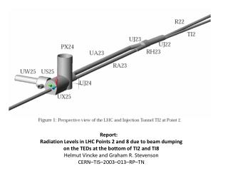
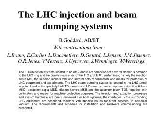
The LHC injection and beam dumping systems The LHC injection systems located in points 2 and 8 are comprised of several elements common to the LHC ring and the downstream ends of the TI 2 and TI 8 transfer lines, namely the injection septa MSI, the injection kickers MKI and several sets of collimators and masks for protection of LHC equipment and experiments. The LHC beam dumping system is located in the LHC tunnel in point 6 and in the specially built TD tunnels and UD caverns, and comprises extraction kickers MKD, extraction septa MSD, dilution kickers MKB and the absorber block TDE, together with collimators and masks for machine protection purposes. The injection and extraction processes and system hardware are briefly reviewed. For both systems, the interfaces to the surrounding LHC equipment are described, together with specific issues for other services, in particular vacuum. The requirements and schedule for installation and hardware commissioning are presented. B.Goddard, AB/BT With contributions from : L.Bruno, E.Carlier, L.Ducimetiere, D.Gerard, L.Jensen, J.M.Jimenez, O.R.Jones, V.Mertens, J.Uythoven, J.Wenninger, W.Weterings.
Outline • For both systems… • Generalities, layout • The injection/extraction process • Equipment subsystems • General issues • Interfaces • Commissioning requirements • Schedule • Summary
The injection process H LHC orbit 12 mrad Require: < 1ms rise time (gap between SPS injections), <3 ms fall time (abort gap), 8 ms flat-top length (1 SPS batch) Kicker (V) Q5 Septum (H) V LHC orbit 1.24 mrad 0.39 mrad
Layout (point 8) 5 x MSI septa 4 x MKI kickers TDI collimator TCDD absorber
Injection septum MSI Circulating beam Vacuum chamber • 5 units of 2 types per injection • 4 m unit length • Total of 12 mrad (H) • ~DC during injection • Circ. chamber : Cu + m metal screen, baked to 250ºC. • Issues: • Inj. chamber positioning • Aperture for injected beam/ septum protection (TCDI) • Vacuum interconnect details Extracted beam Vacuum chamber Status: Magnets series 100% complete ?? Vacuum chamber – prototype OK Laminated yoke Magnet coil
Injection kicker MKI • 4 units per injection • Total of 0.85 mrad (V) • 2.65 m unit length • 0.9 / 3.0 ms rise / fall time • Metallized ceramic vacuum chamber • Issues • Flashover failure (1 ‘dangerous’ per ~10Y…) Prototype in recuperated ZL tank Status: Prototyping completed (Mag.+Gen.) Magnets series ~20% complete Generators series ~60% complete Transmission lines ~10% complete
TDI collimator • Setting - ±10 y (~ ±5 mm) • 4m jaw length – in recuperated ZL tank • < 300 mm non-flatness • Materials – hBN, Al, Cu • Issues: • Bakeout + beam screen • Loading at injection (OP scenarios) • hBN properties after irradiation Status: Conceptual design completed Prototyping of subassemblies ongoing
TCDD absorber • ~35 x 60 mm (V, H) • Setting ±10 x,y • 1m Cu jaw length • Protects D1 from damage / quench • Still in conceptual design phase • Issues • Fixed / movable jaws? (larger in IP8) • Finalise requirements Status: Conceptual design ongoing
Beam instrumentation (IP 8) BPM BTV (OTR) BCT BLM Status: Standard LHC items – progress OK
System specific issues remaining • Injection collimation system to be finalized (machine protection, collimators, performance); • Injection system (+ LTI) failure modes to be quantified (define LHC collimator loading at injection); • Overall injection oscillations (1.5 s budget) to be quantified (including SPS and transfer lines); • Detailed integration with ICL/MIWG • Details of installation sequencing / schedulewith EST/IC • HW commissioning aspects with EST/IC & HCWG • Beam commissioning (sector test?) aspects with AB/OP & LHC-OP
Interfaces • Circulating beam vacuum (BI, MSI, MKI, TDI, TCDD) • Injection line vacuum (BI, MSI) • Machine Protection (BIC); • SPS (injection sequences, interlocks); • PO (magnet powering); • CV (MKI, MSI cooling) • RF (Revolution Frequency); • Controls system (settings, alarms, timing, postmortem, logging, …); • Safety (fire detection, access); • Collimators (interdependence of settings with TCDI, TDI);
HW commissioning requirements • General services (cooling water, ventilation, power, emergency stops, phones,…) • All equipment installed and individually tested • Sufficient test time in schedule; • Controlled access conditions (tunnel + galleries); • Other systems operational: • Vacuum; • Machine Interlock (beam permit); • Controls (ethernet, pre-pulse, timing, control room s/w, trims, alarms, logging, post-mortem, sequencer, …); • Connection to dump kickers (via BIC + direct);
Schedule required dates as a function of main LHC milestones (rev 1.7) Injection point 8 (UA87): • Hardware installation completed Q4 – 2005 • Hardware commissioning Q1 – 2006 with sector 8.1 • Sector test and injection test (?) Q2 – 2006 Injection point 2 (UA23): • Hardware installation completed Q3 – 2006 • Hardware commissioning in Q1 – 2007 with sector 1.2 and TI 2
TCDQ 40 m Schematic layout TDE dump block 10 x MKB kickers 15 x MSD septa 15 x MKD kickers Total length : 975m from MKD to TDE TCDS protection TCDQ protection
The extraction process 0.06 mrad H Require: <3 ms extraction kicker rise time (abort gap), >89 ms extraction kicker flat-top length (full LHC turn) LHC orbit 0.33 mrad Septum (V) Q4 Kicker (H) V 2.4 mrad LHC orbit
Extraction kicker MKD Prototype magnet Ceramic vacuum chamber • 15 units per beam • Total of 0.27 mrad (H) • Generators : redundancy, retriggering, self-diagnostics • Impedance : metallized ceramic vacuum chamber • Issues: • Failure rates (missing, pre-triggering) Conductor Strip-wound Core Status: Small prototype tested OK (M+G) Magnet series at ~20% Generator series at ~20% Transmission lines at ~10%
Extraction septum MSD • 15 units (3 types) per beam • Total of 2.4 mrad (V) • Circ. Chamber to 250ºC • Issues: • Aperture for circ / extr beam (investigating larger circ. chamber in MSDC, ±4 mm orbit interlock) • Reworking of connection boxes (QRL interference) • Details of vac. interconnects Magnet coil Extracted beam Vacuum chamber Circulating beam Vacuum chamber Status: Magnet prototypes tested OK Magnet series ~60% complete Vacuum chamber prototyping Laminated yoke
Dilution kickers MKB Strip Wound Core • 10 units per beam (4 x H, 6 x V) • ± 0.28 mrad (H), ± 0.28 mrad (V) • Reuse MKD technology • Issues: • Staged installation (4/10 units) limits LHC intensity to 50% (for ~2 years after green light) Conductor Status: M+G detailed design in progress Transmission line series at ~10% Vacuum Tank
Dump core TDE • 7m long C / C-C TDE in steel shrink-cylinder, followed by 1m Al, 2m Fe • ~1000 T of concrete shielding • Issues: - Containment (N2 overpressure, possible additional TD diluter?) - No water-cooling (staged) limits power deposition Status: Concrete shielding finished TDE detailed design completed First TDE unit being assembled Ancillary equipment design ongoing
Protection elements TCDS/TCDQ • TCDS – 6m fixed diluter, C, C-C, AlN, Ti • TCDQ – 9.5m mobile diluter, C, Al • Issues: - Vacuum + impedance issues with C, AlN - TCDQ interdependence with collimators, MP Status: TCDS detailed design started TCDQ in conceptual design phase
Beam instrumentation Status: FS being finalized (mostly standard LHC items except large BTVs and electronics for dedicated position interlock BPMs). BPM Position Interlock BPM BLMs Plus – 2 BCTs per line at MKB – 4 screens (OTR) per line at MSD, MKB, (TD), TDE
Extracted beam (TD) vacuum pipe • ~640m long • 110/2 mm -> 610/6.3 mm Status: ES being finalized Integration studies started System be built under Indian collaboration agreement
System specific issues remaining • Overall reliability analysis • Energy tracking of MKD, MSD, MKB • MSD aperture • Machine protection (TCDQ settings, additional interlock BPM functionality) • Loading of collimators (asynchronous dump) • Detailed integration with ICL/MIWG • Details of installation sequencing / schedulewith EST/IC • HW commissioning aspects with EST/IC & HCWG • Beam commissioning aspects with AB/OP & LHC-OP
Interfaces • Circulating beam vacuum (BI, MKD, MSD, TCDS, TCDQ) • Extraction line vacuum (BI, MSD, MKB, TD62/8, TDE) • Machine Protection (BIC); • PO (magnet powering, DCCTs for Beam Energy Meter); • CV (TCDS, TCDQ, TDE, MSD cooling, TD/UD ventilation) • RF (Revolution Frequency and abort gap synchronisation); • Controls system (settings, alarms, timing, postmortem, logging, …); • Safety (fire detection, access, Emergency stops); • Collimators (interdependence of settings with TCDQ);
HW commissioning requirements • General services (cooling water, ventilation, power, emergency stops, phones, …) • All equipment installed and individually tested • Sufficient test time in schedule; • Controlled access conditions (tunnel + galleries); • Other systems operational: • Vacuum; • Machine Interlock (beam permit); • Beam Energy Meter; • Controls (ethernet, pre-pulse, timing, control room s/w, trims, alarms, logging, post-mortem, sequencer, …); • Connection to injection kickers (via BIC + direct);
Schedule required dates as a function of main LHC milestones (rev 1.7) Beam Dumping System UA63, TD62 tunnel, UD62: • Hardware installation completed Q2 – 2006 • Hardware commissioning in Q3 – 2006, with sector 5.6 Beam Dumping System UA67, TD68 tunnel, UD68: • Hardware installation completed Q3 – 2006 • Hardware commissioning in Q4 – 2006, with sector 6.7 The Beam Dumping System also needs to have a “reliability run” (system validation, check failure/availability predictions, debugging of system, INB, …).For this run the system will have to be connected in their proper operational way: UA63 to TD68, UA67 to TD62. • Period foreseen: Q1 – 2007 (together with HC sector 1.2.) • Estimated time required for a useful reliability run: 3 months.
Conclusions Injection system • Hardware production on schedule for main LHC milestones • Outstanding issues include • Some collimation and machine protection aspects • TCDD conceptual design to be finalised • Detailed interaction with LHC collimators • Installation, h/w and beam commissioning aspects Beam dumping system • Hardware production on schedule for main LHC milestones • Outstanding issues include • Reliability analysis and details of dedicated reliability run • TCDQ conceptual design to be finalised • Detailed interaction with LHC collimators • Installation, h/w and beam commissioning aspects