Download
1 / 49
500 likes | 690 Views
P09321 DETAILED DESIGN REVIEW ELECTRICAL/SOFTWARE/ FIRMWARE SYSTEMS. Felix Feliz Matthew Jones Michael Boquard Rebecca Jaiven Justin Zagorski Shuaib Mansoori. 1. OVERVIEW. Project Intro & Dispenser Layout Embedded System Selection Firmware Data Flow User Access Levels GUI Mock Ups

E N D
P09321 DETAILED DESIGN REVIEWELECTRICAL/SOFTWARE/ FIRMWARE SYSTEMS Felix Feliz Matthew Jones Michael Boquard Rebecca Jaiven Justin Zagorski Shuaib Mansoori 1
OVERVIEW Project Intro & Dispenser Layout Embedded System Selection Firmware Data Flow User Access Levels GUI Mock Ups EE Dispensing System MSDII Timeline Issues Appendix 2
INTRO – PROJECT DESCRIPTION • Produce a robust prototype that dispenses medication on a time-bases to patients in a secure and accountable environment. • Allow to dispense a week’s supply of up to 6 different pills for two patients accessed twice daily. • Reliable and compact electro-mechanical dispensing system that can be controlled by a common laptop. 3
MECHANICAL LAYOUT Lid Empty Return Lid Cylinder Holder/ Latch Support Rail Leg (Collapsible) Ramp (Collapsible) 5
OVERVIEW Project Intro & Dispenser Layout Embedded System Selection Firmware Data Flow User Access Levels GUI Mock Ups EE Dispensing System MSDII Timeline Issues Appendix 8
EMBEDDED SYSTEM SELECTION • Field Programmable Gate Array (FPGA) • USB Microcontroller • EEPROM FPGA SELECTION 9
XEM3001 10
XEM3001 • Pro’s • One of the cheapest • Built in USB FPGA interface • High level of support and tools (SDK’s and API’s) • Good number of I/O Pins • Familiar with Xilinx Spartan 3 FPGA’s • Con’s • Hard to solder (easier than the other three) • Has male-female connectors that attach to the holes • Needs to be programmed at start • Easy to reprogram with provided SDK (one line of code!) 11
EEPROM COMPARISON: PARALLEL OR SERIAL Parallel Series Pro’s Smaller footprint (only about 8 pins) Smaller power consumption (good if an onboard battery is used) Faster access time Cheaper Con’s More complexity involved in writing/reading data from EEPROM • Pro’s • Easiest to write to • Higher memory density • Better AC performance • Con’s • Very large foot print (Size of 2N bits requires N pins, for addressing, and other pins for power, select, etc) • Higher power consumption • Costly 12 Conclusion: Series Two different kinds of serial, SPI and I2C
EEPROM COMPARISON: SPI OR I2C I2C SPI Pro’s Faster Full-duplex Less overhead than I2C due to no addressing Con’s More devices requires more wires and more hardware • Pro’s • Easier to implement multiple devices on same bus • Communicate with on-board infrequently used devices easily • Con’s • High complexity compared to SPI • Half-duplex 13 Conclusion: SPI Component Selected: Spansion 8-Mbit SPI EEPROM
OVERVIEW Project Intro & Dispenser Layout Embedded System Selection Firmware Data Flow User Access Levels GUI Mock Ups EE Dispensing System MSDII Timeline Issues Appendix 14
OVERVIEW Project Intro & Dispenser Layout Embedded System Selection Firmware Data Flow User Access Levels GUI Mock Ups EE Dispensing System MSDII Timeline Issues Appendix 17
LEVELS OF USER ACCESS • Super User • Direct access to each solenoid • Can check and clear SmartCartridge™ Memory • User Access Control • Connect and remove SmartCartridge™ • Set SmartCartridge™ Settings • Pulse time of solenoid • Sensor Sensitivity
LEVELS OF USER ACCESS – CONT. • Administrator • User Access Control • Check SmartCartridge™ History • Connect and remove cartridge • Pharmacist • Check SmartCartridge™ History • Add and adjust medication • Connect and remove cartridge • Delivery • Connect and remove cartridge
LEVELS OF USER ACCESS – CONT. • Caregiver • Can dispense medication for patient under caregiver’s care • Patient • Can dispense own medication
OVERVIEW Project Intro & Dispenser Layout Embedded System Selection Firmware Data Flow User Access Levels GUI Mock Ups EE Dispensing System MSDII Timeline Issues Appendix 21
OVERVIEW Project Intro & Dispenser Layout Embedded System Selection Firmware Data Flow User Access Levels GUI Mock Ups EE Dispensing System MSDII Timeline Issues Appendix 29
EXISTING ELECTRICAL DISPENSING SYSTEM 30 Appendix D: Schematics
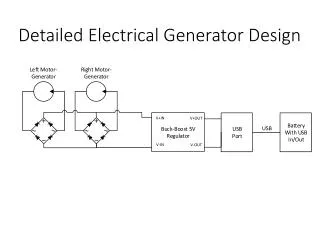
PROPOSED ELECTRICAL DISPENSING SYSTEM 31 Appendix XXXXX: Schematics
POWER BUDGET 33
ADDITIONS TO DISPENSING CIRCUITRY Sensors Buzzer 37
Connections and Cabling • Input to PCB Board: • 2 Conductors, 3 Contacts • From Driver: • Cable Ribbon to Nitinol Arrays 40
OVERVIEW Project Intro & Dispenser Layout Embedded System Selection Firmware Data Flow User Access Levels GUI Mock Ups EE Dispensing System MSDII Timeline Issues Appendix 41
OVERVIEW Project Intro & Dispenser Layout Embedded System Selection Firmware Data Flow User Access Levels GUI Mock Ups EE Dispensing System MSDII Timeline Issues Appendix 43
ISSUES • Sensor’s Sensitivity • Cabling properly • Timeline for prototyping and PCB • Constant Current Controller • MOSFET vs. Bipolar devices 44
OVERVIEW Project Intro & Dispenser Layout Embedded System Selection Firmware Data Flow User Access Levels GUI Mock Ups EE Dispensing System MSDII Timeline Issues Appendix 45
APPENDIX 46
Typically has 8-bit data bus Address bus large enough to cover complete address range Ex. 1024 addresses = 210 addresses, so 10 bits for a data bus To Write: Enable Write with Address Selected Disable Write when data is asserted on data pins To Read: Enable Read with Address Selected Read data asserted on data pins Definition of Parallel EEPROM
2 wire-input Serial Data (SDA) Serial Clock (SCL) Communication Process Master sends start condition Master sends unique 7-bit address of the slave Master sends read/write bit (0 – write, 1 – read) Receiver (Master when read, slave when write) sends “ACK”nowledgement Transmitter (Master when write, slave when read) transmits 1 byte Receiver sends ack (repeats till stop) Definition of Serial I2C