Download
1 / 46
460 likes | 542 Views
Explore the TCP/IP protocol layers, including the physical, data link, internet, host-to-host, and application layers. Learn about IP addresses, subnetting, and address masks in this comprehensive guide to networking protocols.

E N D
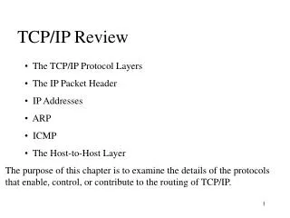
TCP/IP Review • The TCP/IP Protocol Layers • The IP Packet Header • IP Addresses • ARP • ICMP • The Host-to-Host Layer The purpose of this chapter is to examine the details of the protocols that enable, control, or contribute to the routing of TCP/IP.
Thephysical layer The protocols of this layer fall within four categories that together describe all aspects of physical media: • Electrical/optical protocols describe signal characteristics such as voltage or photonic levels, bit timing, encoding, and signal shape. • Mechanical protocols are specifications such as the dimensions of a connector or the metallic makeup of a wire. • Functional protocols describe what something does. For example, "Request to Send" is the functional description of pin 4 of an EIA-232-D connector. • Procedural protocols describe how something is done. For example, a binary 1 is represented on an EIA-232-D lead as a voltage more negative than –3 volts.
The data link layer • how the medium is accessed and shared, how devices on the medium are identified, and how data is framed before being transmitted on the medium. Examples of data link protocols are IEEE 802.3/Ethernet, IEEE 802.5/Token Ring, and FDDI.
Theinternet layer • corresponding to the OSI network layer, is primarily responsible for enabling the routing of data across logical internetwork paths.
The host-to-host layer • Corresponding to the OSI transport layer, specifies the protocols that control the internet layer, much as the data link layer controls the physical layer. • the transport layer controls traffic on the logical link the end-to-end connection of two devices whose logical connection traverses a series of data links.
The application layer • The most common services of the application layer provide the interfaces by which user applications access the network.
IP Addresses • IP addresses are 32 bits long; like all network-level addresses, they have a network portion and a host portion. • The network portion uniquely identifies the data link (that is, the network) and is common to all devices attached to the network. • The host portion uniquely identifies a particular device attached to the network.
IP Addresses • The dotted-decimal format is a convenient way to write IP addresses, but it should not be confused with what the router (or host) sees—a 32-bit string.
The First Octet Rule Without putting too fine a point on it, it can be said that there are three sizes of internetworks as measured by the number of hosts: big, medium, and small. • Big internetworks, by definition, have a huge number of hosts. Relatively few big internetworks exist. • Small internetworks are just the opposite. Each one is small because it has a small number of hosts; a huge number of small internetworks exist. • Medium internetworks are just that: a medium number of them (in relation to big and small ones) and a medium number of hosts in each one.
The First Octet Rule • Class A, B, and C IP address formats.
The First Octet Rule No. of Hosts 2^24= 16,777,216 2^16=65536 2^8= 256
Address Masks • Each bit of this class B address is ANDed with the corresponding bit of the address mask to derive the network address.
Address Masks • An address and mask are assigned to an interface of a Cisco router (in this example, the E0 interface) by means of the following commands: Smokey(config)# interface ethernet 0 Smokey(config-if)# ip address 172.21.35.17 255.255.0.0
Subnets and subnet Masks • If a separate class A, B, or C address were assigned to each data link, less than 17 million data links could be addressed before all IP addresses were depleted. This approach is obviously impractical. • The only way to make class A, B, or C addresses practical is by dividing each major address, such as 172.21.0.0, into subnetwork addresses. Recall two facts: • The host portion of an address can be used as desired. • The network portion of an IP address is determined by the address mask assigned to that interface.
Subnets and subnet Masks • Subnet masks allow a single network address to be used on multiple data links by "borrowing“ some of the host bits for use as subnet bits.
Subnets and subnet Masks • The IP address now has three parts: the network part, the subnet part, and the host part. The address mask is now a subnet mask, or a mask that is longer than the standard address mask. The first two octets of the address will always be 172.21, but the third octet—whose bits are now subnet bits instead of host bits— may range from 0 to 255. The internetwork in Figure 2.12 has subnets 1, 2, 3, 4, and 5 (172.21.1.0 through 172.21.5.0). Up to 256 subnets may be assigned under the single class B address, using the mask shown.
Subnets and subnet Masks • All routing protocols can not support subnet addresses in which the subnet bits are all zeros or all ones. • The reason is that these protocols, called classful protocols, cannot differentiate between an all-zero subnet and the major network number. For instance, subnet 0 in Figure 2.13 would be 172.21.0.0; the major IP address is also 172.21.0.0. The two cannot be distinguished without further information.
Subnets and subnet Masks • Likewise, classful routing protocols cannot differentiate a broadcast on the all-ones subnet from an all subnets broadcast address.For example, the all-ones subnet in Figure 2.13 would be 172.21.255.0. For that subnet, the all-hosts broadcast address would be 172.21.255.255, but that is also the broadcast for all hosts on all subnets of major network 172.21.0.0. • The subnet mask may be represented in any of three formats—dotted decimal, bitcount, and hexadecimal.
Subnets and subnet Masks • The command ip netmask-format [dec|hex|bit] in line configuration mode. • Gladys(config)# line vty 0 4 • Gladys(config-line)# ip netmask-format bit
Designing Subnets • When designing subnets and their masks, the number of available subnets under a major network address and the number of available hosts on each subnet are both calculated with the same formula: • 2 n – 2 • where n is the number of bits in the subnet or host space. For example, given a class A address of 10.0.0.0, a subnet mask of 10.0.0.0/16 (255.255.0.0) means that the 8-bit subnet space will yield 28 – 2 = 254 available subnets and 216 – 2 = 65,534 host addresses available on each of those subnets.
Designing Subnets • A stepwise method for designing subnets • Determine how many subnets are required and how many hosts per subnet are required. • Use the 2 n – 2 formula to determine the number of subnet bits and the number of host bits that will satisfy the requirements established in step 1. • Working in binary, determine all available bit combinations in the subnet space; in each instance, set all the host bits to zero. Convert the resulting subnet addresses to dotted decimal. These are the subnet addresses. • 4. For each subnet address, again working in binary, write all possible bit combinations for the host space without changing the subnet bits. Convert the results to dotted decimal; these are the host addresses available for each subnet.
Designing Subnets • A class B address across 500 data links, each with a maximum of 100 hosts? • This requirement is easily met, but only by using nine bits in the subnet field: 29 – 2 = 510 available subnets, leaving seven bits for the host field, and 27 – 2 = 126 available hosts per subnet.
Designing Subnets Example: • Step 1: • The network from Figure but with a class C mask assigned. Subnetting an entire octet will not work here; there would be no space left for host bits.
Designing Subnets • Step2: Applying the 2n – 2 formula, three subnet bits and five host bits will satisfy the requirements: 23 – 2 = 6 and 25 – 2 = 30. A class C mask with three bits of subnetting is represented as 255.255.255.224 in dotted decimal.
Designing Subnets • Step 3: • The subnet bits are derived by marking the masked subnet bit space and then writing all possible bit combinations in the space by counting up from zero in binary.
Designing Subnets • Step 3: Continue.. Figure.The subnet addresses are derived by filling in the network address to the left of the subnet space, setting all host bits to zero to the right of the subnet space, and converting the results to dotted decimal.
Designing Subnets • The host addresses for a subnet are derived by writing all possible bit combinations in the host space. These are the host bits for subnet 192.168.100.32.
Designing Subnets Step 4: Continue..
Troubleshooting a Subnets Mask • Given an IP address and a subnet mask, follow these steps to find the subnet, the broadcast, and the host addresses.
Address Resolution Protocol • ARP is used to map a device's data link identifier to its IP address. • A device needing to discover the data link identifier of another device will create an ARP Request packet. This request will contain the IP address of the device in question (the target) and the source IP address and data link identifier (MAC address) of the device making the request (the sender). • The ARP Request packet is then encapsulated in a frame with the sender's MAC address as the source and a broadcast address for the destination
ARP Continue.. • The broadcast address means that all devices on the data link will receive the frame and examine the encapsulated packet. All devices except the target will recognize that the packet is not for them and will drop the packet. The target will send an ARP Reply to the source address, supplying its MAC address
ARP Continue.. • An analyzer capture of the ARP Request depicted in Figure 2.20, with its encapsulating frame.
ARP Continue.. An analyzer capture of the ARP Reply depicted in Figure 2.20.
ARP Continue.. The ARP table for three devices connected to the same network: a Cisco router, a Windows 95 host, and a Linux host.
Proxy ARP • In Figure2.26, The router is configured with a 28-bit mask (four bits of subnetting for the class C address), but the hosts are all configured with 24-bit, default class C mask. As a result, the hosts will not be aware that subnets exist. Host 192.168.20.66, wanting to send a packet to 192.168.20.25, will issue an ARP Request. • The router, recognizing that the target address is on another subnet, will respond with its own hardware address. Proxy ARP makes the subnetted network topology transparent to the hosts. • Proxy ARP is enabled by default on Cisco routers and may be disabled on a per interface basis with the command no ip proxy-arp.
Proxy ARP • Proxy ARP enables the use of transparent subnets.
Reverse ARP • Instead of mapping a hardware address to a known IP address, Reverse ARP (RARP) maps an IP address to a known hardware address. • Some devices, such as diskless workstations, may not know their IP address at startup. RARP may be programmed into firmware on these devices, allowing them to issue an ARP Request that has their burned-in hardware address. • The reply from a RARP server will supply the appropriate IP address.
ICMP • The Internet Control Message Protocol, or ICMP, specifies a variety of messages whose common purpose is to manage the internetwork. ICMP messages may be classified as either error messages or queries and responses. • The packets are identified by type; many of the packet types have more specific types, and these are identified by the code field. • Table 2.5 lists the various ICMP packet types and their codes.
The Host-to-Host Layer • The internet layer is responsible for the logical paths between networks, the host-to-host layer is responsible for the full logical path between two hosts on disparate networks. • From another viewpoint, the host-to-host layer is an interface to the lower layers of the protocol suite, freeing applications from any concern about how their data is actually being delivered. • The two primary services offered by the host-to-host layer are TCP and UDP.
TCP • The Transmission Control Protocol provides applications with a reliable, connection-oriented service. In other words, TCP provides the appearance of a point-to-point connection. • Point-to-point connections have two characteristics: • They have only one path to the destination. A packet entering one end of the connection cannot become lost, because the only place to go is the other end. • Packets arrive in the same order in which they are sent.
TCP • The internet layer does not guarantee that all packets will take the same route, and therefore there is no guarantee that they will arrive in the same sequence and time intervals as they were sent, or that they will arrive at all. • A telephone call is connection-oriented service. Data must arrive sequentially and reliably, or it is useless. Like a telephone call, TCP must first establish a connection, then transfer data, and then perform a disconnect when the data transfer is complete.
UDP • User Datagram Protocol provides a connectionless, best-effort packet delivery service. • The advantage of UDP, however, is that no time is spent • setting up a connection—the data is just sent.
Looking Ahead • The focus of this chapter has largely been on the mechanisms by which a device's internet layer (or OSI network layer) identifies itself and how it maps to the network interface (or OSI data link) layer. • Internet layer functions that are important to routing were also examined. • The following chapter examines the routing function and the information a router requires to perform that function.