Download
1 / 9
100 likes | 140 Views
Understand the two main methods of modeling electrical systems: Kirchhoff's point rule and applying Lagrange equation. Learn about passive (L, C, R) and active (op-amp) elements, mathematical models, and analogies between mechanics and electrics. Discover analogies between translational and rotational systems and apply Lagrange equations to both. Dive into the energy equations for inductors, capacitors, resistors, and springs while exploring the similarities and differences between mechanical and electrical quantities.

E N D
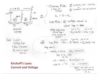
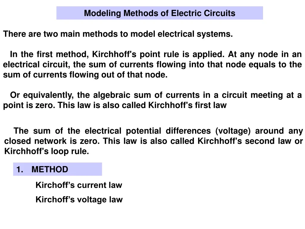
Modeling Methods of Electric Circuits There are two main methods to modelelectrical systems. In the first method, Kirchhoff's point rule is applied. At any node in an electrical circuit, the sum of currents flowing into that node equals to the sum of currents flowing out of that node. Or equivalently, the algebraic sum of currents in a circuit meeting at a point is zero. This law is also called Kirchhoff's first law The sum of the electrical potential differences (voltage) around any closed network is zero. This law is also called Kirchhoff's second law or Kirchhoff's loop rule. • METHOD Kirchoff’s current law Kirchoff’s voltage law
In the second method, Kirchhoff's point rule is applied.By Kirchhoff's first law, the algebraic sum of currents in a circuit meeting at a point will be zero. The expressions of total magnetic energy, electrical energy, and virtual work are written for the system. Then, Lagrange equation is applied. In this course, the second method is used. 2. METHOD Current law Magnetic energy, electric energy, virtual work. Lagrange equation In this course, 2th Method will be applied.
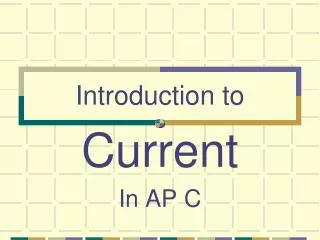
L R C - + BASIC ELECTRIC CIRCUIT ELEMENTS Passive Elements In electrical systems, there are three passive elements, which are inductor L, capacitor C, resistor R. Active Elements In this course, op-amp will be introduced here as an active element. Op-amp’s properties will be explained in the future examples.
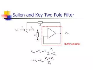
The mathematical models of passive elements can be given with an analogy between mechanics and electrics. The elements and their definitions in mechanics and electrics are given below. There is an analogy among the quantities in the columns.Mass and inductor have the same equations and the elements and their equationsare given below, respectively. Kinetic and magnetic energy equations are written for mass and inductor. Mechanical-Electrical Analogy .. .
Spring and capacitor have the same equations.The equations for these elements are given below, respectively. Potenatial and electric energy equations are written forspring and capacitor elements. Mechanical-Electrical Analogy . ..
Damper and resistor have the same equations.The equations for these elements are given below, respectively. The virtual work equations are written fordamper and resistorelements. Mechanical-Electrical Analogy . ..
Analogy in Mechanical (Translational and Rotational) and Electrical Systems The table shows an analogy among the mechanical and electrical systems. There is also an analogy between the translational and rotational mechanical quantities. There are general coordinates in mechanical systems, whereas there are general charges in electrical systems. Lagrange equations are applied to both of mechanical and electrical systems. . .. . ..
E2 E1 There is an analogy among the quantities in the columns. Definitions for fluid and thermal systems will be given in next courses.
Difference among the forces which act on a system makes a body translate. Difference among the moments makes the body rotate. Potential difference generates current in electrical circuits. E1, the first type of energy in Lagrange equation can be stored in moving elements in mechanical systems and inductors in electrical systems. E2, the second type of energy in Lagrange equation can be stored in springs in mechanical systems and capacitors in electrical systems.