Download
1 / 48
480 likes | 651 Views
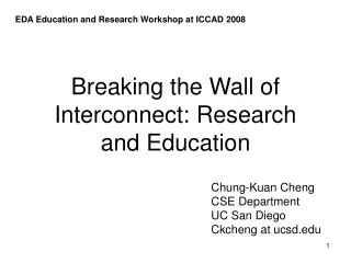
EDA Education and Research Workshop at ICCAD 2008. Breaking the Wall of Interconnect: Research and Education. Chung-Kuan Cheng CSE Department UC San Diego Ckcheng at ucsd.edu. Outlines. Technology Trend Interconnect: RC Segments + Buffers

E N D
EDA Education and Research Workshop at ICCAD 2008 Breaking the Wall of Interconnect: Research and Education Chung-Kuan Cheng CSE Department UC San Diego Ckcheng at ucsd.edu
Outlines • Technology Trend • Interconnect: RC Segments + Buffers • Interconnect: Transmission Lines + Buffers (On-Chip) • Research and Education Directions • Hands-on Experiences • Conclusion
90nm 45nm 22nm global wire global wire global wire m1 wire m1 wire m1 wire
Interconnect: RC Segments + Buffers Delay comparison of wires (metal 1 and global) vs. gates
Interconnect: RC Segments (Energy per Bit) Energy comparison of wires (metal 1 and global) vs. gates
Interconnect: RC Segments (Delay Energy Product) Delay energy product comparison of wires (metal 1 and global) vs. gates
Interconnect: RC Segments (Bandwidth) Bandwidth comparison of wires (metal 1 and global) vs. gates
Repeated RC Segments • Analytical formula based flow implemented in MATLAB [3] • Parameters: • a=0.4, b=0.7: constants related to transistor switching model • f=1: ratio of diffusion capacitance to gate capacitance of transistor • g=1.34: P/N ratio of transistor width • Technology variables: • r0: output resistance of min-sized inverter;rw: wire resistance per unit length • cmos: min-sized NMOS gate capacitance;cw: wire capacitance per unit length • Design objects: min-d, min-dp, min-d2p * Data are computed using formula in [3] based on wire parameters of ITRS report 2007 [1]
Performance metrics of repeated wire • Normalized delay: • Normalized power (energy/bit): • Leakage power factor: • Normalized delay power product: • Bandwidth:
Optimum repeater insertion for minimizing delay • Optimum repeater interval and size: • Optimum delay and power
Theory (Telegrapher’s Equation) • Telegrapher’s equation: • Propagation Constant: • Wave Propagation: • Alpha and Beta corresponds to speed and phase velocity. 18
On-Chip Transmission Line (1) • Operation Region • RC region: • LC region: • Two parameters used to verify the region[17] • Upper bound of wire length for lumped element modeling • Corner frequency between RC and LC region 19
T-line Structure and Extraction • Single-ended strip-line configuration • Wire length: 5mm • Extraction includes 3 adjacent wires to consider crosstalk • Use H=1.2um(2.4um) for C extraction and H=4.4um(8.8um) for L extraction, to consider the worst case
Experimental Settings • Tools • 2D EM-field solver CZ2D from EIP tool suite of IBM • Frequency dependent RLGC tabular model • HSPICE with predictive transistor model • Synopsys level3 MOSFET model • Design flow is implemented in MATLAB • Case configuration • Study and compare the performance metrics of 3 schemes at 45nm node • Using the worst-case input pattern -+- to simulate delay/power. • Optimize under 3 object functions: min-d/min-dp/min-d2p
Effect of driver impedance and termination resistance on wire output eye-opening Effect of driver impedance on wire bandwidth Wire Bandwidth and Eye-Opening
Performance Comparison • Rs:10ohm, Wire:16X for scheme 2 and 3
Effect of RS on Step Response Wire 16X, w/ termination resistance Rload=220ohm
Effect of Rload on Step Response (Optimal Value) Wire 16X, w/ termination resistance RS=10ohm
Eye-diagrams of T-line scheme • w/ termination resistance • Rload=220ohm • Optimal solution of min-ddp
Interconnect Dominated Designs: Research Directions • Analysis: Simulation from wires, circuits, to systems • Wires and device elements: modeling, extraction and measurement • Circuits: • Spice simulation of whole circuits • Power analysis • Timing analysis (LOCV) • Systems: • Buses and interfaces • Function and logic analysis • Rapid prototyping and emulation • Multi-domain analysis: EM, thermal, mechanical, biological analysis • Synthesis: Design from wires, buses, layouts, modules, to networks • RC segments, transmission lines, photonic communication • Power systems, clock distributions, signal buses • Physical layout: floorplanning, placement and routing • Function module synthesis • Network architectures
Interconnect Dominated Designs: Education Computer Sciences Software Engineering Algorithms and Numerical Methods Logic and Arithmetic Designs Computer and Network Architectures Distributed Computation Electrical Engineering Physics (Photonics) EM Waves Circuit Theory VLSI Designs Motivations and Methodologies
Education: Motivations and Methodologies Data Mining: Literature, Patents, Products, Packages, Research Groups Problem Solving Statement of the Problems Hands-on Experience Debugging Communication Teaming Networking Broadcasting
Education: Hands-on Experience • Y. Zhu, T. Weng, C.K. Cheng, "Enhancing Learning Effectivelness in Digital Design Courses by Programmable Logic Boards," to appear in IEEE Trans. on Education. • T. Weng, Y. Zhu, and C.K. Cheng, "Digital Design and Programmable Logic Boards: Do Students Actually Learn More?" ASEE/IEEE Frontiers in Education Conf., Session S1H-1, pp. 1-6, 2008.
Education: Hands-on Experience Introduction Class Information Teaching Experience Students Feedback Final Exam Results Conclusion
Hands-on Experience: Example Digital design is an essential part of the CS curriculum Challenges in teaching Lack of previous hardware class work Lack of interest in hardware among CS students EDA Software Process vs Hardware Execution
Hands-on Experience: Example Concerns Whether CS students have proper background? How difficult to teach VHDL and integrate it into courses? Board prices & Teaching load Benefits Students can gain better understanding, grasp full design implementation cycle (Zema 1998, Areibi 2001, Vera et al. 2006, etc.)
Class Structure Introductory digital logic design course in CS program at UCSD Combinational & sequential logic Standard modules: decoders, MUX… System design Associated labs Altera Quartus II software UP-2 CPLD board (100 US$) Schematic & VHDL designs
Lab Assignments 1. Combinatorial Circuit Design:5 basic circuits (adder, multiplexer) 2. Sequential Circuit Design: Shift registers, counters, clock 3. Finite State Machines:traffic light, train controller, grey counter 4. CPU Design
Teaching Goals & Methodologies 1. Utilize the PLD board to promote learning for the students Design labs to reflect the teaching materials 2. Design labs that are enjoyable and educational for the students Design labs that are novel and have a degree of fun to them
Students Feedback Survey structure 16 statements to evaluate (1: strongly disagree, 5: strongly agree) 14 short-answer questions Conducted in the end of the term 35 returned out of 38 students (92.1%)
Students Feedback 1 – PLD board usefulness 86% enjoyed using the PLD board 9% enjoyed running simulations 80% felt that they learned digital logic from using the board 23% felt they learned from using the simulations 77% agree PLD board helped them learn digital design
Students Feedback 1 – PLD board usefulness 63% stated that they would not have learned the contents as well without the board 26% said they would have spent a lot of time and effort to grasp the knowledge without the board 4% thought the boards were not useful
Students’ Words “I thought it was really neat to be able to see the number 32 instead of 10000 with high and lows in a timing diagram” “it (the PLD board) allowed me to apply concepts learned in the class in a real world situation and understand how people in the industry go about using these concepts to solve these problems” “(The CPU design project is enjoyable) because I got to build an actual CPU so that I could get a feel of what low level programming is like”
Students’ Words (cont.) “This class is very useful and I have learned a lot from it, especially lab 4 because I really got to see how things are done” “At first I thought it would just be another class to drag myself to everyday. However, I now have a great appreciation for digital design. So much so that I am considering a career on it.”
Final Exam Score Comparison Compare the final exam results on CSE140 (Digital Design Theory) between Fall 2005 and Spring 2007 Similar course structures, similar final exams, same instructor
Observations The second tier students benefit most Survey comments indicate that the use of board solidified many of the concepts From students who scored 80-90 100% agreed that they learned more from the board All thought tutorials are useful All but one student said the course was more interesting than they originally expected
Observations We investigated whether using a programmable logic board helps CS students We introduce PLD boards in our labs Students answered a detailed survey They enjoyed the boards Those struggled in the class benefit most Tutorials are important Exam results comparison indicates that middle score range students improved a lot from the boards
Summary • Technology Trend: Interconnect Dominance • Expansion of Literatures and Tools • Classic Theories and New Problems Covering Multiple Disciplines • Motivations and Methodologies • Hands on Experiences 47