FPU
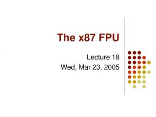
FPU. R. Graue, D. Kampf Kayser-Threde. Primary Structure. Field Mirror for Spectrometer. Collimator housing. Photometer housing. Chopper Cover. Alignment Cube. Blue Spectrometer Connector Panel. Top Optics housing. 4 K Thermal Strap. Entrance to FPU. Bolometer housing. 2 K

FPU
E N D
Presentation Transcript
FPU R. Graue, D. Kampf Kayser-Threde PACS FPU
Primary Structure Field Mirror for Spectrometer Collimator housing Photometer housing Chopper Cover Alignment Cube Blue Spectrometer Connector Panel Top Optics housing 4 K Thermal Strap Entrance to FPU Bolometer housing 2 K Feed Thru FPU foot 2 axis Red Spectrometer Connector Panel Spectrometer housing FPU foot 1 axis PACS FPU
Primary Structure (continued) Alignment Cube Top Optics housing Chopper Cover Field Mirror External Mirror Fixation Peri 1 External Mirror Fixation Collimator housing B_Mirror_2 External Mirror Fixation Photometer housing 2 K Feed Thru 4 K Thermal Strap Grating Connector Panel Bolometer housing Blue Spectrometer Connector Panel FPU foot 3 axis Grating Cover (external mounting of grating) PACS FPU
Primary Structure (continued) FPU foot 1 axis Red Spectrometer Connector Panel Spectrometer Cover FPU foot 2 axis Bolometer housing Blue Spectrometer Connector Panel Collimator housing FPU foot 3 axis Grating Connector Panel Photometer housing Grating Cover (external mounting of grating) PACS FPU
FPU Suspension PACS FPU
Detector Struts Side/Iso View Fibre: T300 Resin: Ciba Geigy Araldit LY-3505 Hardener XP 3403 PACS FPU
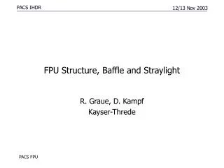
FPU Structure, Baffles and Straylight Entrance Baffle PACS FPU
FPU Structure, Baffles and Straylight Bottom view of TOP OPTICS 1st field stop Aperture Stop (complete closure of entrance compartment) Lyot stop for telescope secondary mirror edge Baffle are shown in brown Chopper: 2nd aperture stop Lyot stop for aperture stop (2nd Lyot stop) Mirror FOLD 5 Closure of Entrance Optics (quasi 2nd field stop) PACS FPU
FPU Structure, Baffles and Straylight Photometer housing seen from Top Optics Entrance to Slicer / Spectrometer Focus Mirror (to Spectrometer) 2nd Field Stop Mirror FOLD 5 from Top Optics scetched Entrance to Photometer Focal planes of photometer PACS FPU
FPU Structure, Baffles and Straylight Bottom view of Photometer housing (interface to bolometer) 4th aperture stop at conic baffle to thedetector arrays not shown 3rd field stop (blue photometer) Separation wall between red and blue compartment contains Dichroic beamsplitter (near 3rd aperture, not accessible) 3rd field stop (red photometer) PACS FPU
FPU Structure, Baffles and Straylight Collimator housing Grating drive Grating PACS FPU
FPU Structure, Baffles and Straylight Slicer seen from Photometer Entrance to slicer / spectrometer Focus Mirror scetched PACS FPU
FPU Structure, Baffles and Straylight Slicer seen from collimator Area blocked by housing Beam to collimator Beam to spectrometer, exit from collimator PACS FPU
FPU Structure, Baffles and Straylight Slicer internal view Focus mirror inside photometer To collimator To spectrometer PACS FPU
FPU Structure, Baffles and Straylight Spectrometer seen from bottom Filter wheel Red spectrometer detector Blue spectrometer detector From slicer / collimator PACS FPU
FPU Structure, Baffles and Straylight Spectrometer seen from bottom Blue spectrometer detector Red spectrometer detector Filter wheel PACS FPU
2K - Feed Through Design Fixation to housing aluminum CFRP Tubes CFRP A: Outside sleeve B: Inside sleeve C: Cold finger D/E: Retainer ring 1/2 F: Muff G: Ring Copper old Finger PACS FPU
IR Coating • Trade Off selection of baseline coating • Material: Suede 3101 with glas beads (deep black, rough surface) • Thickness (average): 430µm • Test verification • BRDF and specular measurements (Delft University) • liquid nitrogen test • contamination test • Outgasing tests (CVCM, TML) to be performed • Problem: (particulates drop off) Solution: Update of procedure (brushing, intermediate drying, materials of layers) PACS FPU
IR Coating - BRDF PACS FPU
IR Coating - Specular reflection PACS FPU
Design Envelope PACS FPU
Optical Bench Interface PACS FPU
Optical Beam Stay Out Envelope PACS FPU
Design and MAIV Status of Structural Items • Top Optics & Slicer manufacturing drawings completed • Top Optics manufacturing in progress • Collimator detailed design completed • Bolometer & Spectrometer detailed design in progress • CFRP Struts (Breadboard) under manufacturing • Cleanroom set up in progress PACS FPU
Documents Status • ICDs • Chopper, FW, Calibration Source, Filters/Dichroics, Ga:Ga Detector, Grating: approved • Bolometer, Distribution Boards: several open points under evaluation • Cryogenic harness : approved • External interface drawing: to be approved • Procurement specifications (structures, mirror, coating, screws/helicoils, Si -lens, emitter for CS , etc.) issued • AIV and functional/environmental test plan issued PACS FPU
PA Activities • Documents • PMP • CIDL • PA Plan • MIP/KIP plan • Inputs to FMECA • Approval of procurement/manufacturing documentation/drawings • Configuration Control PACS FPU
MIP / KIP List • Inspection of FW assembly (CQM/PFM) after functional and environmental verification testing at TTL • Inspection of calibration source (CQM/PFM) after environmental and functional testing at MPE • Inspection of coated mirrors (CQM/PFM) at KT (tbc) • Substructure fit check inspection after manufacturing and coating of aluminium structure (STM/CQM/PFM) at KT • Inspection of all distribution boards and harness after manufacturing and functional testing (CQM/PFM) at KT • Functional performance verification after FPU alignment (CQM/PFM) at KT • FPU performance inspection after vibration tests (CQM/PFM) at MPE PACS FPU
SCHEDULE • Manufacturing • STM/CQM primary/secondary structures thermal treatment /manufacturing /IR coating sequentially to be completed until 7/02 • CQM/PFM optical components to be completed until 6/02 • STM/CQM/PFM CFRP struts and 2 K feed through material test program in progress, manufacturing to be completed until 5/02 • Filter Wheel BB completed, CQMs hardware partly manufactured, tests completed until 8/02 • Calibration source BB component tests in progress, CQMs hardware delivery until 7/02 (tbc) • Distribution board manufacturing to be completed 12/02 (tbc - CPP delivery on critical path) • AIV • STM in 7/02 • CQM from 7/02 to 4/03 PACS FPU
Optical Mirrors PACS FPU
Status of Optical Mirrors • Manufacturing drawings completed (incl. Alignment mirrors) • Coarse manufacturing of CQM/PFM completed • Thermal treatment completed • Optical surface finish in progress • Cryogenic pretests (thermo-optical behavior) of mirror samples completed PACS FPU
Alignment Plan PACS FPU
Alignment Tasks • Optical axis of telescope to FPU (alignment cubes/mirrors) • Top Optics with Calibration Sources and Chopper • Slicer optics • Spectrometer/Collimator optics with Grating Assembly Dummy, Dichroic, FW1, Ge:Ga Detectors • Bolometer optics with Dichroic, FW2 • Integration of bolometer assembly (CEA) PACS FPU
Alignment PlanAKF at centre of the telescope secondary mirror PACS FPU
Alignment PlanAKF and Laser assembly with top optics AKF centered at nominal position of telescope secondary mirror (real aperture) Internal aperture stop Top Optics side view Chopper Intermediate focal plane splitting between spectrometer and photometer section PACS FPU
Alignment PlanCentering alignment of bolometer Intermediate focal plane splitting between spectrometer and photometer section Field Mirror Peri 1 B_Mirror_2 PACS FPU
Alignment PlanBolometer alignment B_Mirror_1 B_Mirror_2 Filter Wheel Bolometer Blue Bolometer focal plane PACS FPU
Alignment PlanSlicer Optics alignment Focus Mirror at intermidate focal plane PACS FPU
Alignment PlanCollimator Alignment PACS FPU
Alignment PlanRed and Blue spectrometer channel alignment PACS FPU
Alignment Status • Updated Alignment plan issued • Alignment procedure engineering in progress • Preliminary OGSE procurement plan • CVSE procurement in progress (cryostat) PACS FPU
OGSE • Autocollimation telescope • Optical mounts • 4 x CCD array with optics • PC with framegrabber • 2 x alignment telescope • 4 x HeNe Laser (laser diode) • Set of pinholes from nickel with LED's (point sources) • Support structure for pinholes • Masks for mirrors (plexiglas with 3 point orientation to the front surface) • Scatter-plates • Lateral translation stages • 2 x Rotary table • Alignment mirrors during alignment (temporary) • Alignment mirrors for FPFPU alignment PACS FPU
Structural and Thermal Analysis PACS FPU
Flip angle Precision of end stop Power dissipation per position change Transition time Operating temperature Warming of parts within view of detector Duty cycle Life time 0° > 180° > 360°(Optionally 90° & 270°) 30 arcmin < 50 mWs 5 sec (average) 3-300 K < 0.1 K (filter wheel assembly requirement, only) 1 per 30 min. 20000 cycles FW Design PACS FPU
Filter Wheel Assembly PACS FPU