Evaluating Hydrogen Retention and Evaporation Challenges in ECR Plasma - FLiNaK Molten Salt Interactions
This research investigates the interactions between electron cyclotron resonance (ECR) plasma and FLiNaK molten salts, focusing on hydrogen retention and the physical and chemical evaporation issues arising from these interactions. The study covers the experimental setup, plasma parameters, and results relating to hydrogen retention over varying interaction times. The findings highlight the potential of using molten salts as plasma-facing materials in fusion devices, offering insights into heat removal and wall condition refreshment while addressing the challenges posed by hydrogen retention and evaporation.

Evaluating Hydrogen Retention and Evaporation Challenges in ECR Plasma - FLiNaK Molten Salt Interactions
E N D
Presentation Transcript
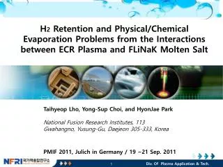
H2 Retention and Physical/Chemical Evaporation Problems from the Interactions between ECR Plasma and FLiNaK Molten Salt TaihyeopLho, Yong-Sup Choi, and HyonJae Park National Fusion Research Institutes, 113 Gwahangno, Yusung-Gu, Daejeon 305-333, Korea PMIF 2011, Julich in Germany / 19 ~21 Sep. 2011 Div. Of Plasma Application & Tech. 1
CONTENTS of PRESENTATION • Introduction - Objectives • Experimental Setup • o Plasma Parameters • o Magnetic field structure • Interaction between the plasma and molten salt (FLiNaK) • oAr plasma • o H2 Plasma • Hydrogen retention • Morphology • Future Plan - Research Load Map
INTRODUCTION - OBJECTIVES • Molten salts have been suggested as the one of the liquid wall • material in a fusion device. • The advantages of the liquid wall materials are heat removal, refreshing • wall conditions and more. • Molten salts have low thermal conductivitywhich indicates low heat transfer to the structure of the device. • In addition, molten salts have low electrical conductivity (~102Ω-1 m-1) which is relatively weak MHD effects on the surface flow comparing to the liquid lithium. • The molten salt also have low chemical reactivity and low evaporation. • However, we don’t know about the possibility of molten salts as a • plasma facing material. • This research aims on the feasibility test of the possibility.
EXPERIMENTAL SET-UP • Overall Review on Molten Salt Exp. System Magnetron ECR Source Process Chamber Magnet Power MagnetronPower Pumping System
EXPERIMENTAL SET-UP Function Gen. 520 mm Resonance Layer Langmuir Probe : ¼ inch one side planar probe 150mm To DAS 640 mm To DAS Thermocouple Focal Length : 750mm Apeture Ratio : f/9.8 Grating : 1800 Gr/mm Resolution : ~ 0.02 nm PM Tube To Pumping System RGA : Stanford Laboratory
174 mm MAGNETIC FIELD STRUCTURE 80 mm 221mm 91mm 25mm 55mm 20mm 55mm Probe position 20 MoltenSalt
PLASMA PARAMETERS ■ Hydrogen Plasma density, Temperature and potential • Cylindrical Langmuir probe • : Diameter 0.5 mm, Length 12 mm • Unmagnetized plasma assumption • : Laframboise Analysis • Hygrogen Plasma
Interaction between Ar ECR plasma and solid FLiNaK Experiment condition Base pressure: 6ⅹ10-6Torr Working pressure: 1mTorr, Ar 16 sccm ECR head input current: 17A Microwave input power: 500 watt Initial FLiNaK temp.: 28 ℃ II. Measured by monochromator Measuring range: 300~850 nm Resolution: 0.275 nm 2000 point
Interaction between Ar ECR plasma and Liquid FLiNaK Experiment condition Base pressure: 6ⅹ10-6Torr Working pressure: 1mTorr, Ar 16 sccm ECR head input current: 17A Microwave input power: 1000 watt Initial FLiNaK temp.: 539 ℃ II. Measured by monochromator Measuring range: 300~850 nm Resolution: 0.275 nm 2000 point
NUMERICAL SIMULATION Resonance Layer Molten salt bath • Ar plasma interaction with the molten salt • Heat load by ions and electrons to the molten salt is about 30kW/m2 MAX • Radial density profile included • ΔT ~ 50℃ after plasma load (initial temperature =500 ℃)
Interaction between H2 ECR plasma and solid FLiNaK Experiment condition Base pressure: 4.3ⅹ10-6Torr Working pressure: 1mTorr, H2 46 sccm ECR head input current: 17A Microwave input power: 500 watt Initial FLiNaK temp.: 15 ℃ II. Measured by monochromator Measuring range: 300~850 nm Resolution: 0.275 nm 2000point
Interaction between H2 ECR plasma and liquid FLiNaK Experiment condition Base pressure: 3.9ⅹ10-6Torr Working pressure: 1mTorr, H2 57 sccm ECR head input current: 17A Microwave input power: 500 watt Initial FLiNaK temp.: 539 ℃ II. Measured by monochromator Measuring range: 200~850 nm Resolution: 0.2 nm 3250 point
EDS ANALYSIS - MORPHOLOGY • EDS analysis before the interaction
RGA CALIBRATION • RGA can detect the elements from the molten salt even though without the plasma interaction. • Need RGA calibration for hydrogen retention to find the total amount of hydrogen retention. H2 Pressure (Torr) Time (sec)
RGA DATA – HF MEASUREMENT Plasma irradiation time Plasma irradiation time 10min 5min Plasma irradiation time 20min • The potasium is the main element from the molten salt evaporation . • Hydrogen fluoride formation increase with plasma interaction time. • It is possibly come from the chemical formation of HF.
H2 RETENTION - RESULTS H2 retention depends on the interaction time with H2 Plasma • Measured the partial pressure of out-gassed H2from the molten salt surface • as a reference without plasma interaction. • The difference between the measured lines and reference have been • integrated with the time to convert into the total amount of the • hydrogen molecules retention.
H2 RETENTION - RESULTS • Hydrogen retention mainly result from the ion flux into the molten salts. • If the charge exchange which is the high energy neutral particle formation process in the pre-sheath is considered, the retention ratio will be decreased by factor 2. • Considering only the ion bombardment on the Molten Salt • Considering on High Energy Neutral Particles by the Charge Exchange in the Pre-sheath
SUMMARY and FUTURE PLANS • Sodium and Potasium are main impurities from the molten salt. • Fluorine forms the Hydrogen fluoride molecules, which is very corrosive, by chemical reaction at the surface of molten salt or in the bulk plasma. • The composition of the molten salt changed with the interaction time and the position of molten salt. • The amount of hydrogen retention in the molten salt is about 30-40% when the charge exchange in the pre-sheath not included. • We need to understand some issues in the near future • The analysis methods to evaluate the composition of the molten salt. • Physical properties, especially viscosity of molten salt, after plasma interaction. • The impurities from the molten salt, quantitatively. • Influence of HF to the structure.
CONCEPTUAL DESIGN OF THE FLOWING SYSTEM • Roughly request minimum • Molten Salt over 4kg • Conceptual design parameters • for the flowing system ECR Helicon 2 1170 mm 1 3 • Helicon and ECR are the • candidates of the plasma sources 3 4 1030 mm
FUTURE PLANS – ROAD MAP • Molten Salt exp. in a Torus device from 2020 ? 2020 - • CPC will move to the new site in 2012. • The flowing system of the molten salt will be built. • New molten salt, such as FLiBe, FLiNaBe, will be studied from 2018 2018 2015 2010 2012 • The linear device will be operated in 2015.