Download

1 / 26
311 likes | 1.79k Views
Absorption and Stripping of Dilute Mixtures. Chapter6. Purpose and Requirements: Know Equipment of Absorption and Stripping Learn to Design a trayed Tower and a packed Tower. Key and Difficult Points: Key Points Equipment of Absorption and Stripping

E N D
Purpose and Requirements: • Know Equipment of Absorption and Stripping • Learn to Design a trayed Tower and a packed Tower Key and Difficult Points: Key Points • Equipment of Absorption and Stripping • Graphical Equilibrium-Stage Method for Trayed Towers • Algebraic Method for Trayed Towers • Rate-Based Method for Packed Towers Difficult Points • Algebraic Method for Trayed Towers • Rate-Based Method for Packed Towers
Outline • 6.1 EQUIPMENT • 6.2 GENERAL DESIGN CONSIDERATIONS • 6.3 GRAPHICAL EQUILIBRIUM-STAGE METHOD FOR TRAYED TOWERS • 6.4 ALGEBRAIC METHOD FOR DETERMINING THE NUMBER OF EQUILIBRIUM STAGES • 6.5 STAGE EFFICIENCY • 6.6 TRAY CAPACITY, PRESSURE DROP, AND MASS TRANSFER • 6.7 RATE-BASED METHOD FOR PACKED COLUMNS • 6.8 PACKED COLUMN EFFICIENCY, CAPACITY, AND PRESSURE DROP • 6.9 CONCENTRATED SOLUTIONS IN PACKED COLUMNS
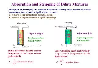
Absorption (Gas Absorption/Gas Scrubbing/Gas Washing吸收) • Gas Mixture (Solutes or Absorbate) • Liquid (Solvent or Absorbent) • Separate Gas Mixtures • Remove Impurities, Contaminants, Pollutants, or Catalyst Poisons from a Gas(H2S/Natural Gas) • Recover Valuable Chemicals
Physical Absorption • Chemical Absorption (Reactive Absorption) Figure 6.1 Typical Absorption Process
Absorption Factor(A吸收因子) • A = L/KV Component A = L/KV K-value Water 1.7 0.031 Acetone 1.38 2.0 Oxygen 0.00006 45,000 Nitrogen 0.00003 90,000 Argon 0.00008 35,000 • Larger the value of A,Fewer the number of stages required • 1.25 to 2.0 ,1.4 being a frequently recommended value
Stripping(Desorption解吸) • Stripping • Distillation • Stripping Factor(S解吸因子) • S = 1/ A= KV/L High temperature Low pressure is desirable Optimum stripping factor :1.4.
6.1 EQUIPMENT trayed tower packed column bubble column spray tower centrifugal contactor Figure 6.2 Industrial Equipment for Absorption and Stripping
Trayed Tower(Plate Clolumns板式塔) Figure 6.3 Details of a contacting tray in a trayed tower
(a) perforation (b) valve cap (c) bubble cap (d) Tray with valve caps Figure 6.4 Three types of tray openings for passage of vapor up into liquid
Froth Liquid carries no vapor bubbles to the tray below Vapor carries no liquid droplets to the tray above No weeping of liquid through the openings of the tray Equilibrium between the exiting vapor and liquid phases is approached on each tray. (a) Spray(b) Froth(c) Emulsion(d) Bubble(e)Cellular Foam Figure 6.5 Possible vapor-liquid flow regimes for a contacting tray
Packed Columns Figure 6.6 Details of internals used in a packed column
More surface area for mass transfer • Higher flow capacity • Lower pressure drop Packing Materails (a) Random Packing Materials (b) Structured Packing Materials • Expensive • Far less pressure drop • Higher efficiency and capacity Figure 6.7 Typical materials used in a packed column
6.2 ABSORBER/STRIPPER DESIGN • 6.2.1 General Design Considerations • 6.2.2 Trayed Towers • 6.2.2.1 Graphical Equilibrium-Stage • 6.2.2.2 Algebraic Method for Determining the Number of Equilibrium • 6.2.2.3 Stage Efficiency • 6.2.3 Packed Columns • 6.2.3.1 Rate-based Method • 6.2.3.2 Packed Column Efficiency, Capacity, and Pressure Drop
6.2.1 General Design Considerations Design or analysis of an absorber (or stripper) requires consideration of a number of factors, including: 1. Entering gas (liquid) flow rate, composition, temperature, and pressure 2. Desired degree of recovery of one or more solutes 3. Choice of absorbent (stripping agent) 4. Operating pressure and temperature, and allowable gas pressure drop 5. Minimum absorbent (stripping agent) flow rate and actual absorbent (stripping agent) flow rate as a multiple of the minimum rate needed to make the separation 6. Number of equilibrium stages 7. Heat effects and need for cooling (heating) 8. Type of absorber (stripper) equipment 9. Height of absorber (stripper) 10. Diameter of absorber (stripper)
SUMMARY • 1. A liquid can be used to selectively absorb one or more components from a gas mixture. A gas can be used to selectively desorb or strip one or more components from a liquid mixture. • 2. The fraction of a component that can be absorbed or stripped in a countercurrent cascade depends on the number of equilibrium stages and the absorption facto: A = L/KV, or the stripping factor, S = KV/L, respectively. • 3. Absorption and stripping are most commonly conducted in trayed towers equipped with sieve or valve trays, or in towers packed with random or structured packings. • 4. Absorbers are most effectively operated at high pressure and low temperature. The reverse is true for stripping. However, high costs of gas compression, refrigeration and vacuum often preclude operation at the most thermodynamically favorable conditions. • 5. For a given gas flow rate and composition, a desired degree of absorption of one or more components, a choice of absorbent, and an operating temperature and pressure, there is a minimum absorbent flow rate, given by (6-9) to (6-11), that corresponds to the use of an infinite number of equilibrium stages. For the use of a finite and reasonable number of stages, an absorbent rate of 1.5 times the minimum ' is typical. A similar criterion, (6-12), holds for a stripper.
6. The number of equilibrium stages required for a selected absorbent or stripping agent flow rate for the absorption or stripping of a dilute solution can be determined from the equilibrium line, (6-1), and an operating line, (6-3) or (6-5), using graphical algebraic, or numerical methods. Graphical methods, such as Figure 6.11, offer considerable visual insight into stage-by-stage changes in compositions of the gas and liquid streams. • 7. Rough estimates of overall stage efficiency, defined by (6-21), can be made with the correlations of Drickamer and Bradford, (6-22), O'Connell, (6-23), and Figure 6.15 More accurate and reliable procedures involve the use of a small Oldershaw column , or semitheoretical equations, e.g., of Chan and Fair, based on mass transfer considerations, to determine a Murphree vapor-point efficiency, (6-30), from which a Murphrtf vapor tray efficiency can be estimated from (6-31) to (6-34), which can then be related to the overall efficiency using (6-37). • 8. Tray diameter can be determined from (6-44) based on entrainment flooding considerations using Figure 6.24. Tray vapor pressure drop, the weeping constraint, entrainment, and downcomer backup can be estimated from (6-45), (6-64), (6-65), (6-66), respectively.
9. Packed column height can be estimated using the HETP, (6-69), or HTU/NTU,(6-85), concepts, with the latter having a more fundamental theoretical basis in the two-film theory of mass transfer. For straight equilibrium and operating lines, HETP is related to the HTU by (6-90), and the number of equilibrium stages is related to the NTU by (6-91). • 10. Below a so-called loading point, in a preloading region, the liquid holdup in a packed column is independent of the vapor velocity. The loading point is typically about 70% of the flooding point and most packed columns are designed to operate in the preloading region at from 50% to 70% of flooding. From the GPDC chart of Figure 6.36, the flooding point can be estimated, from which the column diameter can be determined with (6-98
11. One significant advantage of a packed column is its relatively low pressure drop per unit of packed height, as compared to a trayed tower. Packed column pressure drop can be roughly estimated from Figure 6.36 or more accurately from (6-100). • 12. Numerous rules of thumb are available for estimating the HETP of packed columns. However, the preferred approach is to estimate hog from separate semitheoretical mass transfer correlations for the liquid and gas phases, such as those of (6-123) and (6-124) based on the extensive experimental work of Billet and Schultes. • 13. Determination of theoretical stages for concentrated solutions involves numerical integration because of curved equilibrium and/or operating lines.
REFERENCES • 1. Washburn, E.W., Ed.-in-Chief, International Critical Tables, McGraw-Hill, New York, Vol. Ill, p. 255 (1928). • 2. Lockett, M., Distillation Tray Fundamentals, Cambridge University Press, Cambridge, UK, p. 13 (1986). • 3. Okoniewski, B.A., Chem. Eng. Prog., 88 (2), 89-93 (1992). • 4 Sax, N.I., Dangerous Properties of Industrial Materials, 4th ed., Van Nostrand Reinhold, New York, pp. 440-441 (1975). • 5. Lewis, W.K., Ind. Eng. Chem., 14, 492-497 (1922). • 6. Drickamer, H.G., and J.R. Bradford, Trans. AICHE, 39, 319-360 (1943). • 7. Jackson, R.M., and T.K. Sherwood, Trans. AIChE, 37, 959(1941). • 8. S- O'Connell, H.E., Trans. AIChE, 42, 741-755 (1946). • 9.Walter, J.F., and T.K. Sherwood, Ind. Eng. Chem., 33, 493-XH (1941). • 10. Edmister, W.C., The Petroleum Engineer, C45-C54 (Jan. 1949).
11. Lockhart, F.J., and C.W. Leggett, in K.A. Kobe and J.J. McKetta, Jr., Ed., Advances in Petroleum Chemistry and Refining,vol. 1, Interscience, New York, Vol. 1, pp. 323-326 (1958). • 12. Holland, C.D., Multicomponent Distillation, Prentice-Hall, Englewood Cliffs. NJ, 1963. • 13. Murphree, E.V., Ind. Eng. Chem., 17, 747 (1925). • 14. Hausen, H., Chem. Ing. Tech., 25, 595 (1953). • 15.Standart, G., Chem Eng. ScL, 20, 611 (1965). • 16.Lewis, W.K., Ind. Eng. Chem., 28, 399 (1936). • 17. Gerster, J.A., A.B. Hill, N.H. Hochgraf, and D.G. Robinson, Tray Efficiencies in Distillation Columns," Final Report from the University of Delaware, American Institute of Chemical Engineers, V* York (1958). • 18. Bubble-Tray Design Manual, AIChE, New York (1958). • 19.Gilbert. T.J., Chem. Eng. ScL, 10, 243 (1959). • 20.Barker, P.E., and M.F. Self, Chem. Eng. ScL, 17, 541 (1962).
21. Bennett, D.L., and H.J. Grimm, AIChE J., 37, 589 (1991). • 22. O'dershaw, C.F., Ind. Eng. Chem. Anal. Ed., 13, 265 (1941). • 23.Fair. J.R., H.R. Null, and W.L. Holies, Ind. Eng. Chem. Process Des.Dev., 22, 53-58 (1983). • 24.Souders, M., and G.G. Brown, Ind. Eng. Chem., 26, 98-103 (1934). • 25.Fair,J.R., Peiro/Chem. Eng., 33, 211-218 (Sept. 1961). • 26. Sherwood, T.K., G.H. Shipley, and F.A.L. Holloway, Ind. Eng. Chem., 30, 765-769 (1938). • 27. Glitsch Ballast Tray, Bulletin No. 159, Fritz W. Glitsch and Sons, Dallas, TX (from FRI report of Sept. 3, 1958). • 28. Glitsch V-l Ballast Tray, Bulletin No. 160, Fritz W. Glitsch and Sons, Dallas, TX (from FRI report of Sept. 25, 1959). • 29. Oliver, E.D., Diffusional Separation Processes. Theory, Design, and Evaluation, John Wiley and Sons, New York, pp. 320-321 (1966). • 30. Bennett, D.L., R. Agrawal, and P.J. Cook, AIChE J., 29, 434-442 (1983).
31. Smith, B.D., Design of Equilibrium Stage Processes, McGraw-Hill, New York (1963). • 32. Klein, G.F., Chem. Eng., 89 (9), 81-85 (1982). • 33. Kister, H.Z., Distillation Design, McGraw-Hill, New York (1992). • 34. Lockett, M.J., Distillation Tray Fundamentals, Cambridge University Press, Cambridge, UK, p. 146 (1986). • 35. American Institute of Chemical Engineers (AIChE), Bubble-Tray Design Manual, AIChE, New York, (1958). • 36. Chan, H., and J.R. Fair, Ind. Eng. Chem. Process Des. Dev., 23,814-819 (1984). • 37. Chan, H., and J.R. Fair, Ind. Eng. Chem. Process Des. Dev., 23,820-827 (1984). • 38. Scheffe, R.D., and R.H. Weiland, Ind. Eng. Chem. Res., 26,228-236 (1987). • 39. Foss, A.S., and J.A. Gerster, Chem. Eng. Prog., 52, 28-J to34-J (Jan. 1956). • 40. Gerster, J.A., A.B. Hill, N.N. Hochgraf, and D.G. Robinson, "Tray Efficiencies in Distillation Columns," Final Report from University of Delaware, American Institute of Chemical Engineers (AIChE), New York (1958).
41. Fair, J.R., Petro./Chem. Eng., 33 (10), 45 (1961). • 42. Colburn, A.P., Ind. Eng. Chem., 28, 526 (1936). • 43. Chilton, T.H., and A.P. Colburn, Ind. Eng. Chem., 27, 255-260, 904 (1935). • 44. Colburn, A.P., Trans. AIChE, 35, 211-236, 587-591 (1939). • 45. Billet, R., Packed Column Analysis and Design, Ruhr-University Bochum (1989). • 46. Stichlmair, J., J.L. Bravo, and J.R. Fair, Gas Separation and Purification, 3, 19-28 (1989). • 47. Billet, R., and M. Schultes, Packed Towers in Processing and Environmental Technology, translated by J. W. Fullarton, VCH Publishers, New York (1995). • 48. Leva, M., Chem. Eng. Prog. Symp. Ser., 50 (10). 51 (1954). • 49. Leva, M., Chem. Eng. Prog., 88, (1) 65-72 (1992). • 50. Kister, H.Z., and D.R. Gill, Chem. Eng. Prog., 87 (2), 32-42(1991).
51. Billet, R., and M. Schultes, Chem. Eng. Technoi, 14, 89-95(1991). • 52. Ergun, S., Chem. Eng. Prog., 48 (2), 89-94 (1952). • 53. Kunesh, J.G., Can. J. Chem. Eng., 65, 907-913 (1987). • 54. Whitman, W.G., Chem. and Met. Eng., 29, 146-148 (1923). • 55. Sherwood, T.K., and F.A.L. Holloway, Tram. AIChE., 36,39-70 (1940). • 56. Cornell, D., W.G. Knapp, and J.R. Fair, Chem. Eng. Prog., 56(7) 68-74 (1960). • 57. Cornell, D., W.G. Knapp, and J.R. Fair, Chem. Eng., Prog., 56(8), 48-53 (1960). • 58. Bolles, W.L., and J.R. Fair, Inst. Chem. Eng. Symp. $er 3/35 (1979). • 59. Bolles, W.L., and J.R. Fair, Chem. £>ig.,89(14), 109-116 (1982) • 60. Bravo, J.L., and J.R. Fair. Ind. Eng. Chem. Process Des.Devel.21,162-170(1982).
61. Bravo, J.L., J.A. Rocha, and J.R. Fair, Hydrocarbon Processing 64 (1), 56-60 (1985). • 62. Fair, J.R., and J.L. Bravo, Chem. E. Symp. Ser., 104, A183-A201 (1987). • 63. Fair, J.R., and J.L. Bravo, Chem. Eng. Prog., 86 (1). 19-29 (1990). • 64. Shulman, H.L., C.F. UHrich, A.Z. Proulx, and J.O. Zimmerm, AIChE J., 1, 253-258 (1955). • 65. Onda, K., H. Takeuchi, and Y.J. Okumoto, J. Chem. Eng .jpn., 1, 56-62 (1968). • 66. Billet, R., Chem. Eng. Prog., 63 (9), 53-65 (1967). • 67. Billet, R., and M. Schultes, Beitrage zur Verfahrens-Und Umweltechnik, Ruhr-Universitat Bochum. pp. 88-106 (1991). • 68. Higbie, R., Trans. AIChE, 31, 365-389 (1935).