Download
1 / 42
1.11k likes | 3.19k Views
Absorption and Stripping of Dilute Mixtures. Absorption and stripping are common methods for causing mass transfer of various components from a gas to a liquid or vise versa to: (a) remove of impurities from gas (absorption) (b) remove of impurities from a liquid (stripping). S 愈大效率愈佳.

E N D
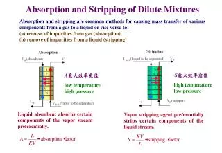
Absorption and Stripping of Dilute Mixtures Absorption and stripping are common methods for causing mass transfer of various components from a gas to a liquid or vise versa to: (a) remove of impurities from gas (absorption) (b) remove of impurities from a liquid (stripping) S愈大效率愈佳 A愈大效率愈佳 high temperature low pressure low temperature high pressure Liquid absorbent absorbs certain components of the vapor stream preferentially. Vapor stripping agent preferentially strips certain components of the liquid stream.
Chemical reaction can ~increase the rate of absorption ~increase the absorption capacity of the solvent ~increase selectively to preferential dissolve only certain components of the gas ~convert a hazardous chemical to a safe compound
~Liquid flows across each tray, over an outlet weir, and into a downcomer, which takes the liquid by gravity to the tray below. ~Gas flow upward through openings in each tray, bubbling through the liquid on the tray. (a)sprayregime: the gas phase is continuous, occurs for weir heights at high gas rates. (b)frothregime: the liquid phase is continuous and the gas passes through in the form of jets or a series of bubbles. (c)emulsionregime: at high liquid rates, small gas bubbles may be undesirably emulsified. (d)bubbleregime: the liquid is fairly quiescent and bubbles rise in swarms, occurs for low gas rates. (e)foamregime: If bubble coalescence is hindered, an undesirable foam forms.
~The simplest is perforations, usually 1/8 to 1/2 in. in diameter, used in a so-called sieve tray (also called a perforated tray). ~A valve tray has much larger openings, commonly from 1.5 to 2 in. in diameter. Each hole is fitted with a valve that consists of a cap, which overlaps the hole, with legs or a cage to limit the vertical rise while maintaining the horizontal location of the valve. With no vapor flow, each valve sits on the tray, over a hole. As the vapor rate is increased, the valve rises, providing a larger peripheral opening for vapor to flow into the liquid to crease a froth. ~A bubble-cap valve has bubble caps that consist of a fixed cap, 3 to 6 in. diameter, mounted over and above a riser of 2 to 3 in. in diameter. The cap has rectangular or triangular slots cut around its side. The vapor flows up through the tray opening into the riser, turns around, and passes out through the slots of the cap, into the liquid to form a froth.
~At the limiting vapor capacity, flooding of the column occurs because of excessive entrainment causing the liquid flow rate to exceed the capacity of the downcomer and, thus, go back up the column. ~At low vapor rates, weeping of liquid through the tray openings or vapor pulsation becomes excessive. ~Because of their low relative cost, sieve trays are preferred unless flexibility is required, in which case valve tray are best. ~Bubble-cap trays, which exist in many pre-1950 installation, are rarely specified for new installations, but may be preferred when the amount of liquid holdup on a tray must be controlled to provide adequate residence time for a chemical reaction or when weeping must be prevented.
~A packed column is a vertical cylindrical pressure vessel containing one or more sections of a packing material over whose surface the liquid flows downward by gravity, as film or as droplets between packing elements. ~Vapor flows upward through the wetted packing, contacting the liquid. ~The sections of packing are contained between a lower-gas- injection support plate, which holds the packing, and an upper grid or mesh hold-down plate, which prevents packing movement. ~A liquid distributor, placed above the hold-down plate, ensures uniform distribution of liquid as it enters the packed section. If the depth of packing is more than about 20 ft, liquid channeling may occur, causing the liquid to flow down the column mainly near the wall, and the gas to flow mainly up the center of the column, thus greatly reducing the extent of vapor-liquid contact. In that case, a liquid redistributor should be installed.
~Most random packings are available in nominal diameters, ranging from 1 in. to 3.5 in. ~As packing size increase, mass transfer efficiency and pressure drop decrease. Therefore, an optimal packing size exists that represents a compromise between these two factors, since low pressure drop and high mass transfer rates are both desirable. ~To minimize channeling of liquid, the nominal diameter of the packing should be less than one- eighth of the column diameter. ~Metal packings are usually preferred because of their superior strength and good wettability. ~Ceramic packings, which have superior wettability but inferior strength, are used only to resist corrosion at elevated temperature, where plastics would fail. ~Plastic packings, usually of polypropylene, are inexpensive and have sufficient strength, but may experience poor wettability, particularly at low liquid rates.
Structured packings come with different size openings between adjacent corrugated layers and are stacked in the column. Although structured packings are considerably more expensive per unit volume than random packings, structured packings exhibit far less pressure drop per theoretical stage and have higher efficiency and capacity.
設計良好的吸收塔或氣提塔應具有的性能 • 讓氣液兩相充分接觸,促進分離效率 • 操作彈性大(turn down ratio高) 即當塔的負荷變動較大時,蒸餾塔的操作仍然穩定,效率變化不大。 • 降低流體流動的阻力,即降低塔內的壓力降 • 氣液處理量大 • 結構簡單可靠,金屬耗用量小,硬體成本低 • 易於操作
填充物性能指標 氣體動能因子 氣相負荷因子
General Design Considerations 1. Entering gas or liquid flow rate, composition, temperature and pressure 2. Desired degree of recovery of one or more solutes 3. Choice of absorbent (stripping agent) 4. Operating pressure and temperature and allowable pressure drop 5. Minimum absorbent (stripping agent) flow rate 6. Number of equilibrium stages 7. Heat effects and need for cooling (heating) 8. Type of absorber (stripper) equipment 9. Height of absorber (stripper) 10. Diameter of absorber (stripper)
Absorbent should: 1. Have a high degree of solubility for the solute (minimizes absorbent required) 2. Have low volatility (increases solute recovery and reduces absorbent loss) 3. Be stable (reduces need to replace absorbent) 4. Be noncorrosive (reduces need for corrosion resistant equipment) 5. Have low viscosity (reduces pressure drop and pump requirements, increase mass flow) 6. Be nonfoaming when in gas contact (reduces size of equipment) 7. Be nontoxic and nonflammable (safety) 8. Be available from the process (reduces cost, reduces need for external source)
Graphical Equilibrium-Stage Method for Trayed Towers Operating Conditions: A) Isobaric B) Isothermal C) Continuous D) Steady flow Assume 1.equilibrium between vapor and liquid flow streams leaving a tray 2.the only component transferred from one phase to the other is the solute. L’ = molar flow rate of solute-free absorbent G’ = molar flow rate of solute-free gas X = mole ratio of solute to solute-free absorbent in the liquid Y = mole ratio of solute to solute-free gas in the vapor
Absorption A mass balance around the first n stages (where n is an arbitrary interior stage) gives: Solute in stage 1 Solute in stage 1 Solute in stage n Solute in stage n Solving for Yn+1 gives the operating line: Operating line is above the equilibrium line because for each stage there is more solute in the vapor than the equilibrium amount for any given liquid solute concentration.
Stripping A mass balance around the first n stages (where n is an arbitrary interior stage) gives: Solute in stage n Solute in stage n Solute in stage 1 Solute in stage 1 Solving for Yn gives the operating line: Operating line is below the equilibrium line because for each stage there is more solute in the liquid than the equilibrium amount for any given vapor solute concentration.
Minimum Absorbent Flow Rate A material balance around the entire absorber gives: Solving for L’: Solving for L’min requires substituting in XN from the equilibrium relationship. As the operating line moves from 1 to 4, the number of required equilibrium stages, N, increases from zero to infinity.
Number of Equilibrium Stages As the slope (L’/G’) is increased, fewer equilibrium stages are required.As (L’/G’) is decreased, more stage are required until (L’min/G’) is reached, at which the operating line and equilibrium curve intersect at a so-called pitch point, for which an infinite number of stages is required.
Example 6.1 When molasses is fermented to produce a liquor containing ethyl alcohol, a CO2-rich vapor containing a small amount of ethyl alcohol is evolved. The alcohol can be recovered by absorption with water in a sieve-tray tower. For the following conditions, determine the number of equilibrium stages required for countercurrent flow of liquid and gas, assuming isothermal, isobaric conditions in the tower and neglecting mass transfer of all components except ethyl alcohol. Entering gas: 180 kmol/h; 98% CO2, 2% ethyl alcohol; 30 C, 110 kPa Entering liquid absorbent: 100% water; 30C, 110 kPa Required recovery (absorption) of ethyl alcohol: 97% Solution
The amount of ethyl alcohol transferred from the gas to the liquid is 97% of the amount of alcohol in the entering gas The amount of ethyl alcohol remaining in the exiting gas is
Algebraic Method for Determining the Number of Equilibrium Stages The application of a graphical method can become very tedious when (1)the problem specification fixes the number of stages rather than the percent recovery of solute, (2)when more than one solute is being absorbed or stripped, (3)when the best operating conditions of temperature and pressure are to be determined so that the location of the equilibrium curve is unknown, (4)if very low or very high concentration force the graphical construction to the corners of the diagram so that multiple y-x diagrams of varying sizes and dimensions are needed. The Kremser method for single-section cascades is ideal for absorption and stripping of dilute mixtures.
Example 6.2 As discussed by Okoniewski, volatile organic compounds (VOCs) can be stripped from wastewater by air. Such compounds are to be stripped at 70 F and 15 psia from 500 gpm of wastewater with 3,400 scfm of air (standard conditions of 60 F and 1 atm) in an existing tower containing 20 plates. A chemical analysis of the wastewater show three organic chemicals in the amounts shown in the following table. Included are necessary thermodynamic properties from the 1966 Technical Data Book-Petroleum Refining of the American Petroleum Institute. It is desirable that 99.9 % of the total VOCs be stripped, but the plate efficiency of the tower is uncertain, with an estimated range of 5% to 20 %, corresponding to one to four theoretical stages for the 20-plate tower. Calculate and plot the percent stripping of each of the three organic compounds for one, two, three, and four theoretical stages. Under what conditions can we expect to desired degree of stripping? What should be done with the exiting air?
To achieve 99.9% removal of the total VOCs, three theoretical stages are needed, corresponding to the necessity for a 15% stage efficiency in the existing 20-tray tower. It is best to process the exiting air to remove or destroy the VOCs, particularly the benzene, which is a carcinogen. The amount of benzene stripped is (500 gpm)(60 min/h)(3.785 liters/gal)(150 mg/liters)=37.5 lb/h If benzene is valued at $0.30/lb, the annual value is approximately $100,000. It is doubtful that this would justify a recovery technique, such as carbon adsorption. It is perhaps preferable to destroy the VOCs by incineration. For example, the air can be sent to a utility boiler, a waste-heat boiler, or a catalytic incinerator. It is also to be noted that the amount of air was arbitrarily given as 3,400 scfm. To complete the design procedure, various air rates should be investigated. It will also be necessary to verify that, at the chosen air flow rates, no flooding or weeping will occur in the column.
Stage Efficiency ~The assumption of equilibrium with respect to mass transfer, however, is not often reasonable and, for streams leaving a stage, vapor-phase mole fractions are not related to liquid-phase mole fractions simply by thermodynamic K-values. ~To determine the actual number of plates, the number of equilibrium stages must be adjusted with a stage efficiency (plate efficiency or tray efficiency). ~Stage efficiency concepts are applicable to devices in which the phases are contacted and then separated, that is, when discrete stages can be identified. ~Stage efficiency is not applicable to packed column whose efficiency is imbedded into an equipment- and system-dependent parameter such as HETP (height of packing equivalent to a theoretical plate). ~As defined by Lewis, an overall stage (or column) efficiency is Eo=Nt/Na where Eo is the fractional overall stage efficiency, usually less than 1.0; Nt is the calculated number of equilibrium (theoretical) stages; and Na is the actual number of contacting trays of plates (usually greater than Nt) required.
~The overall stage efficiency has found to be a complex function of the 1. Geometry and design of the contacting trays 2. Flow rates and flow paths of vapor and liquid streams 3. Compositions and properties of vapor and liquid streams Note: for well-designed trays and for flow rates near the capacity limit, Eo depends mainly on the physical properties of the vapor and liquid streams. ~Values of Eo can be predicted by any of the following four methods: 1. Comparison with performance data from industrial columns for the same or similar systems 2. Use of empirical efficiency models derived from data on industrial columns 3. Use of semitheoretical models based on mass and heat transfer rates 4. Scale-up from data obtained with laboratory or pilot-plant columns
Performance Data ~gas and liquid feed and product flow rates and compositions ~average column pressure and temperature ~pressures and temperatures at the bottom and top of the column ~number of actual trays, Na ~column diameter ~type of tray ~some details of tray design Eo=Nt/Na n-butane as the key component n-heptane as the key component Eo depend primarily on the molar average liquid viscosity, a key factor for the rate of mass transfer in the liquid phase.
~overall stage efficiency increase with decreasing K-value (increasing solubility in the liquid absorbent). ~For the same molar average liquid viscosity (1.90 cps), the overall stage efficiency is seen to vary from as low as 10.3% for ethylene, the most volatile species considered, to 33.8% for butylene, the least volatile species considered. ~low stage efficiency can occur when the liquid viscosity is high and/or the gas solubility is low (high K-value) ~high stage efficiency can occur when the liquid viscosity is low and/or the gas solubility is high (low K-value)
Empirical Correlations Drickamer and Bradford correlated the overall stage efficiency of the key component absorbed or stripped with just the molar average viscosity of the rich oil (liquid leaving an absorber or liquid entering a stripper) at the average tower temperature over a viscosity range of 0.19 to 1.58 cP. The empirical equation, where Eo is in percent and L is in centipoise, fits the data with average and maximum percent deviation of 10.3% and 41%, respectively. The above equation should not be used for absorption into nonhydrocarbon liquids and is restricted to the range of the data used to develop the correlation.
O’Connell found that the Drickamer-Bradford correlation was inadequate for absorbers and strippers when applied to species covering a wide range of volatility or K-value. An O’Connell-type plot of overall stage efficiency for absorption or stripping in bubble-cap tray columns is given in Figure 6.15. The correlating parameter, suggested by Edmister, is KiMLL/L, where: Ki=K-value of species being absorbed or stripped ML=molecular weight of the liquid L =viscosity of the liquid, cP L =density of the liquid, lb/ft3 Column diameter: 2 in. to 9 ft Average pressure: 14.7 to 485 psia Average temperature: 60 to 138 F Liquid viscosity: 0.22 to 21.5 cP Overall stage efficiency: 0.65 to 69 % The average and maximum deviation of the above equation for the 33 data points of Figure 6.15 are 16.3% and 157%, respectively. More than 50% of the data points, including points for the highest and lowest observed efficiencies, are predicted to within 10%. The K-value and absorbent properties are best evaluate at the end of the tower where the liquid phase is richest in solutes.
~Theory and experimental data show that higher efficiencies are achieved forlonger flow paths. ~For short liquid flow paths, the flowing across the tray is usually completely mixed. ~For longer liquid flow paths, the equivalent of two or more completely mixed, successive liquid zones may be present. The result is a greater average driving force for mass transfer and, thus, a high efficiency–perhaps greater than 100%. ~Athigh liquid rates, long liquid path lengths are undesirable because they lead to excessive hydraulic gradients. Multipass trays, as shown in Figure 6.16a, are used to prevent excessive liquid gradients. ~If the height is greater than 212 ft (equivalent to 100 trays on 24-in. spacing), two or more columns arranged in series may be preferable to a single column. 液量大或塔徑大時需要使用多liquid flow path
Example 6.3 Performance data, given below, for a bubble-cap tray absorber located in a Texas petroleum refinery, were reported by Drickamer and Bradford. Based on these data, back-calculate the overall stage efficiency for n-butane and compare the result with both the Drickamer–Bradford and O’Connell correlations. Lean oil and rich gas enter the tower; rich oil and lean gas leave the tower.
Solution The overall material balance is Total flow into tower = 368+946 = 1,314 lbmol/h Total flow from tower = 525.4+786.9 = 1,312.3 lbmol/h 0.13% error The component material balance for the oil absorbent is Total oil in = 368 lbmol/h Total oil out = (0.7024)(525.4)=369 lbmol/h 0.3% error Rich Gas
Performance data (Kremser method) Drickamer and Bradford correlation tower pressure=79+14.7=93.7 psia average tower temperature=(102+126+108+108)/4=111 F O’Connell correlation KnC4=0.7 ML=250 L =1.4 cP L =141.5/(21+131.5)(62.4)=57.9 lb/ft3
Semitheoretical Models Murphree vapor efficiency model, which is the oldest and most widely used, is derived with the assumptions of (1) uniform compositions in vapor and liquid stream entering each tray, (2) complete mixing of the liquid flowing across the tray such that the liquid is of a uniform concentration, equal to the composition of the liquid leaving the tray and entering the next tray below, (3) plug flow of the vapor passing up through the liquid n=rate of mass transfer for absorption from gas to the liquid KG=overall gas mass transfer coefficient based on a partial pressure driving force a=vapor-liquid interfacial area per volume of combined gas and liquid holdup on the tray Ab=active bubbling area of the tray (total cross-sectional minus liquid downcomer areas) Zf=height of combined gas and liquid holdup on the tray P=total absolute pressure yi=mole fraction of i in the vapor rising up through the liquid yi*=vapor mole fraction of i in equilibrium with the completely mixed liquid on the tray G=molar gas flow rate up through the liquid on the tray
number of overall gas-phase mass transfer units KG, a, P, G, yi* are constant Murphree vapor efficiency is defined as Murphree vapor-point efficiency is defined as Liquid composition varies with distance of travel across a tray, but is uniform in the vertical direction.
For complete mixing of liquid on a tray to give a uniform composition, xi,n, Lewis derived For plug flow of liquid across a tray with no longitudinal diffusion (no mixing of liquid in the horizontal direction), Lewis derived A more realistic, but considerably more complex model that accounts for partial liquid mixing on the tray, as developed by Gerster et al., is ZL is the length of liquid flow path across the tray, DE is the eddy diffusion coefficient in the direction of liquid flow, L is the average liquid residence time on the tray, and u= ZL / L is the mean liquid velocity across the tray.
Lewis showed that when the equilibrium and operating lines are straight, but not necessarily parallel, the overall stage efficiency is related to the Murphree vapor efficiency by =1
Scale-up from Laboratory Data ~When vapor-liquid equilibrium data for a system are unavailable or not well known, and particularly if the system forms a highly nonideal liquid solution with possible formation of azeotropes, tray requirement are best estimated, and the feasibility of achieving the desired degree of separation verified, by conducting laboratory tests. ~A particularly useful apparatus is a small glass or metal sieve-plate column with center-to- side downcomers developed by Oldershaw and shown schematically in Figure 6.20. Oldershaw columns are typically 1 to 2 in. in diameter and can be assembled with almost any number of sieve plates, usually containing 0.035- to 0.043-in. holes with a hole area of approximately 10%. ~It is believed that the small-diameterOldershaw column achieves essentially complete mixing of liquid on each tray, thus permitting the measurement of a point efficiency. ~Somewhat larger efficiencies may be observed in much- larger-diameter columns due to incomplete liquid mixing, which results in a higher Murphree tray efficiency and, therefore, higher overall plate efficiency.
Fair et al. recommend the following conservative scale-up procedure for the Oldershaw column: 1.Determine the flooding point. 2.Establish operation at about 60% of flooding (but 40 to 90 % seems acceptable). 3.Run the system to find a combination of plates and flow rates that gives the desired degree of separation. 4.Assume that the commercial column will require the same number of plates for the same ratio of liquid to vapor molar flow rates. ~If reliable vapor-liquid equilibrium data are available, they can be used with the Oldershaw data to determine the overall column efficiency, Eo. ~Eqs. (*) and (**) can be used to estimate the average point efficiency. ~For the commercial-size column, the Murphree vapor efficiency can be determined from the Oldershaw column point efficiency using eq. (**), which takes into account incomplete liquid mixing. In general, the tray efficiency of the commercial column, depending on the length of the liquid flow path, will be higher than for the Oldershaw column at the same percentage of flooding.
Example 6.4 Assume that the column diameter for the absorption operation of Example 6.1 is 3 ft. If the overall stage efficiency, Eo, is 30% for the absorption of ethyl alcohol, estimate the average Murphree vapor efficiency, EMV, and the possible range of the Murphree vapor- point efficiency, EOV. Solution for complete mixing case for plug flow case EOV lies in the range of 31% to 34%, probably closer to 34% for complete mixing.