Download
1 / 26
260 likes | 378 Views
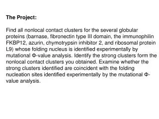
The CANDEL Project aims to develop and launch a carrier designed to house and deploy 12 CanSats. Originating from discussions at the 1998 University Space Systems Symposium with an expected launch in Fall 1999, this project involves universities such as Stanford and the University of Tokyo. Key objectives include deploying CanSats using onboard cameras to capture images and transmitting them to designated locations on Earth, while ensuring safe reentry and burn-up in the atmosphere. The project explores innovative designs and materials for optimal performance.

E N D
The CANDEL Project CANSat DELivery Project Laura Lewis Jens Ramrath Cecil Strickland
Background • Idea originated at the 1998 University Space Systems Symposium • Expected Launch Date - Fall 1999 • Participating Universities Include: Stanford Univ. of Hawaii Univ. of Tokyo Tokyo Inst. Of Tech.
Objectives • Design a carrier to house 12 CanSats • Eject 12 CanSats from carrier • Use onboard camera to view activity during deployment • Transmit pictures to specified location on Earth • Reenter the Earth’s atmosphere • Burn up on reentry
Our first design• Initial Designs • Brainstorm concept at conference
30° Final Deployment Design • Use rotational velocity, , as primary means of deployment • Assist deployment by light springs
200mm 70mm 142mm 382mm CanSat 2-D Design
Carrier Design • Cylindrical case with a 382mm diameter • Cylindrical burrows slightly larger than a “coke” can opening radially outward • Cylindrical area in middle for housing of camera, power, and tracking device • Thin wire covering CanSat openings
Can Attachment • Attached to: • Carrier • Adjacent Cans • Tether Joint
Subsystems Placement • Pressurized canister in the center of the carrier • Provides protection from the space environment • Reduces costs of subsystems
Satellite Subsystems • Camera Suggestions • Tracking Device Suggestions • GPS • NORAD Tracking • Picture Transmittal • Requirements
CameraCMOS Active Pixel Sensor • A single +3.3 V supply • 11 pixel size - 512 x 512 pixel array • Digital I/O • Low noise • Timing and control implemented in chip • Low power (10mW at 1M pixels/sec) • Radiation resistant compared to CCD’s
CMOS Active Pixel Sensor http://csmt.jpl.nasa.gov/APS/features
Dycam Modular Digital Camera • Camera consumes 5V-9V at peak current • Image organization 496 x 288 pixels • Transmits picture to host computer upon request • Camera has its own processor and memory (1 or 4 Megabyte) • In sleep mode camera draws 3.5mA, awake mode 125mA, image capture 650 mA for 15ms • Operated with Dycam’s Picture Viewer Software
Dycam Digital Modular Camera Camera Size: 63 x 24 x 197 mm Weight = 495 grams
Tracking Devices • GPS Options • Simple receiver • Contained in pressurized canister • Determines when pictures will be transmitted to receiver on Earth • Space-hardened • Expensive • NORAD tracking Picture from:www.sni.net
Transmittal Process • GPS • Transmit signal from satellite to receivers on Earth • Transmitter on Earth sends command to send pictures at appropriate time • NORAD tracking • Orbital Elements from NORAD will determine carrier location • Transmitter from Earth sends signal to receiver
Transmittal • Amateur band radio transmitter located on satellite • Device will be used to determine best transmit time to Earth • Various receivers will be placed all over the world to receive pictures
Requirements • Camera Power • CMOS requires 10mW • Dycam requires 5-9 V at 500 mA peak current • Ground Clock for picture transmittal • GPS Power • Power requirements will determine number of batteries needed
CanSat Deployment • CanSats move to final circular position using angular momentum and are restrained by tethers
CanSat Deployment • Carrier is ejected from primary payload • Wire is heated and allows CanSats to eject • CanSats will receive initial acceleration from springs
Manufacturing of Dispenser • Three proposed materials: • Carbon-Epoxy composites • Aluminum • Foam
Advantages of Foam • Very light • Easy to build satellite ourselves • Can withstand vacuum • Possible Temperature and radiation problems • Several different kinds of foam available
Foam • Expanded polystyrene • regular styrofoam • is permanently deformed by impacts • Extruded polystyrene • hard foam • Expanded polypropylene • rubber-like foam • can withstand impacts
Tether There are several possible materials • vectran • UV radiation resistant • zero creep • parachute chord • cheap
Testing the dispenser • Test model in 1-g environment • Test in zero-g onboard NASA KC-135A aircraft (Vomit Comet)