Download
1 / 37
410 likes | 899 Views
The Physics of Lightning. Michael F. Stringfellow. Introduction. The Physics of Lightning: How lightning originates Leader propagation Strike mechanism The return stroke Subsequent strokes Channel multiplicity Lightning flash density Lightning interaction with overhead power lines.

E N D
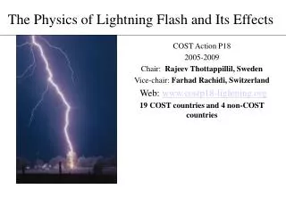
The Physics of Lightning Michael F. Stringfellow 2006 PQIG Workshop
Introduction • The Physics of Lightning: • How lightning originates • Leader propagation • Strike mechanism • The return stroke • Subsequent strokes • Channel multiplicity • Lightning flash density • Lightning interaction with overhead power lines 2006 PQIG Workshop
The Thundercloud 2006 PQIG Workshop
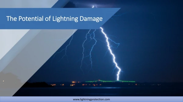
How Lightning Starts • Lightning starts in cloud • Around 0°C - that’s typically 15,000 ft above ground • Breakdown starts in high-field region • Branching discharge moves up and down 2006 PQIG Workshop
Leader Propagation • Ground flashes almost always start with downward (usually) stepped leader from high charge region • Steps 10-100 m long • Pauses between steps • Lowers charge to earth • Negative in > 95% of ground flashes 2006 PQIG Workshop
Connecting Leaders • Launched upward by electric field of stepped leader as it approaches earth • Occur at many locations near descending flash • Most are unsuccessful • One or more connect with downward leader to provide final channel to earth • Not often seen, but frequently heard 2006 PQIG Workshop
Connecting Leaders 2006 PQIG Workshop
Return Stroke • Large current impulse flows to ground • Large electromagnetic pulse radiated • Leader charge neutralized 2006 PQIG Workshop
VHF Radio Picture - First Stroke 2006 PQIG Workshop
Subsequent Strokes • "Dart" leaders launched from cloud • Follow path of first return stroke • Tap new cloud charges • Cause subsequent return strokes • Often depart from old path 2006 PQIG Workshop
VHF Radio Picture Subsequent Stroke 2006 PQIG Workshop
Video Stills of Multi-Stroke Flash 2006 PQIG Workshop
Multiple Stroke Flashes • Typically 2-4 strokes per flash • Stroke intervals 5 -100 milliseconds • Reach ground at 1 to 5 points • Severe flashes have >4 strokes • Continuing currents likely 2006 PQIG Workshop
Multiple Ground Channels • Multiple ground channels are common • Root branching • Simultaneous leader branches • Successive strokes may depart from "main" channel • Three major channels for every two flashes 2006 PQIG Workshop
Multiple Ground Channels 2006 PQIG Workshop
Currents & Voltages • Cloud charging current a few amps • Cloud voltages 50 MV to 500 MV • Leader currents 10 A to 1000 A • Return stroke currents 5kA to 500 kA • Approximately log-normal distribution with 30 kA to 40 kA median 2006 PQIG Workshop
PRODUCTION TRANSMISSION DISTRIBUTION EXTRA HIGH HIGH MEDIUM MEDIUM LOW VOLTAGE VOLTAGE VOLTAGE VOLTAGE VOLTAGE 345-765 kV 115-230kV 24-69kV 120-600V 1 TIE-LINE 2 HEAVY INDUSTRIAL USER MEDIUM INDUSTRIAL SMALL INDUSTRIAL USER TRANSMISSION SUBSTATIONS COMMERCIAL TRANSMISSION SUBSTATIONS RESIDENTIAL POWER DISTRIBUTION INTERCONNECTING SUBSTATIONS PLANTS SUBSTATIONS Electricity Production, Transmission & Distribution 2006 PQIG Workshop
Lightning and Overhead Lines • Direct strikes affect all voltage systems • Problems decrease with insulation level • Flashover when lightning strikes phase conductor • Also back flashover when tower or shield wire struck • Indirect strikes affect distribution and sub-transmission systems • Induced voltages up to 300 kV 2006 PQIG Workshop
Striking Distance • Major influences • Height of structure • Charge on lightning leader • Slenderness of structure • Random effects 2006 PQIG Workshop
Striking Distance • Can be inferred from photographs • Point of last downward branch • Upward connecting leader path • Apparent junction 2006 PQIG Workshop
Voltages from Direct Strikes to Overhead Lines • Stroke to conductor • Conductor has surge impedance of about 400 ohms • Average return stroke current 30 kA • Conductor voltage = 400 x 15,000 V = 6 MV • Stroke to tower • Tower has footing resistance of 30 ohms • Tower voltage = 30 x 30,000 V = 900 kV • Shielding and grounding provide effective protection • Especially for higher voltage systems 2006 PQIG Workshop
Characteristics Shielded construction High insulation levels Good tower grounding Effective protection Well coordinated fast switchgear Result Excellent lightning performance Permanent damage rare Few flashovers quickly cleared by protection Transmission Lines & Lightning 2006 PQIG Workshop
Shielding Effectiveness 2006 PQIG Workshop
Shielding Failure • Likely low current strokes • Less leader charge • Smaller striking distance • Flashover less probable 2006 PQIG Workshop
Characteristics Unshielded construction Low insulation levels Poor pole grounding Less effective protection Slower switchgear, autoreclosers and fuses Result Poor lightning performance Permanent damage common Many flashovers cleared Some may take several shots Nuisance fuse blowing Many sags and short-duration outages Distribution Lines & Lightning 2006 PQIG Workshop
Voltages from Indirect Lightning Strikes 2006 PQIG Workshop
Induced Voltage Flashover 2006 PQIG Workshop
Lightning Transients on AC Power System 2006 PQIG Workshop
Lightning Transients on AC Power System 2006 PQIG Workshop
Some Power System Lightning Problems • Multi-stroke flashes can stress switchgear • Transients occur when open • Multi-channel flashes can defeat system protection • Simultaneous faults occur on different parts of circuit • Frequent strikes in severe storm can overwhelm protection • “Weak-link” structures will flash over frequently • May limit line performance 2006 PQIG Workshop
Lightning Tracking • Radio location used to locate lightning • Real time • Storm warning • Allocation of resources • Archival data • Lightning flash density • Fault investigations 2006 PQIG Workshop
Lightning Incident Investigation 2006 PQIG Workshop
US Flash Density 2006 PQIG Workshop
Highest in southeast & Gulf coast USA Tampa bay 60 per square mile per year Houston 40 per square mile per year Lower as you move north and west Washington & Alaska < 0.1 per square mile per year Phoenix area ~10 per square mile per year Highly variable from year to year Lightning “hot spots” or “lightning nests” Ground Flash Density 2006 PQIG Workshop
Local areas of high lightning incidence Appear over several years’ recording Important to ignore short-term random variations May reflect surface features that steer or promote storms Mountains & rivers Cities Industries May be useful for line performance improvements Shielding Arresters Enhanced grounding Lightning Hot Spots 2006 PQIG Workshop
Phoenix Lightning Ground Flash Density 2006 PQIG Workshop
Summary • Overhead transmission lines are resistant to lightning • Shielded, grounded, high insulation levels • EHV systems are almost immune • Electricity distribution systems are vulnerable • Unshielded, poorly grounded, low insulation levels • Some newly discovered challenges from multi-channel flashes • Lightning location systems have many benefits • Real-time tracking • Archival flash density 2006 PQIG Workshop