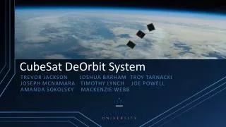
CubeSat Spacecraft Electrical Power System
352 likes | 1.08k Views
CubeSat Spacecraft Electrical Power System. Team Members. Project Members Aleck Wright – Input Power Regulation Matt Churchman – Output Power Regulation Ricky Flores – Solar Array Simulator Sponsor C raig Kief Mentor Sam Monaco. Description.

CubeSat Spacecraft Electrical Power System
E N D
Presentation Transcript
Team Members • Project Members • Aleck Wright – Input Power Regulation • Matt Churchman – Output Power Regulation • Ricky Flores – Solar Array Simulator • Sponsor • Craig Kief • Mentor • Sam Monaco
Description • Create a module that will maximize the power acquired from the CubeSat’s solar arrays • Energy Efficiency • Eclipsed Orbit • Peak Power Tracking • Mounting Configuration • Illumination Level • Temperature • Electrical Load • Orbital Spin
Description Cont. • Input regulators have embedded PPT algorithms • Supervised and augmented with uC • Microcontroller • Bypass Control • Command and Data Handling • Solar Array Simulator • Testing
EPS Block Diagram Unregulated Battery Voltage Relay CTRL Solar Array Input LT Switching Regulator 3.3V BCR 1 Relay Relay CTRL CTRL Solar Array Input Relay BCR 2 LT Switching Regulator 5V Relay CTRL CTRL Solar Array Input LT Linear Regulator 10V BOOST Relay BCR 3 BOOST CTRL
Project Goals • Why design a new EPS? • Extend the operational lifespan of current cube satellites • Reduce dependencies on overseas manufacturers, i.e. Clyde Space • Support and Implement on Trailblazer II • Marketable • What are the functional aspect goals? • “Plug-and-Replace” • User-friendly GUI for SAS, fully documented • Good Telemetry Data
Input Power Regulators Team Member Responsible: Aleck Wright • What do the input regulators do? • The input regulators take in power from the solar arrays and with the help of the PIC microcontroller keep the voltages within their specified ranges • What do we do with that power? • The power will be sent through the output regulators to the external modules on the CubeSat. • The external modules require 3.3V, 5.0V, and 12.0V • What happens in the case of a fault? • In the case of a fault each of the three input regulators will be equipped with a bypass relay maintain input power from the SAS.
Output Power Regulation Team Member Responsible: Matt Churchman • Output Voltage Requirements • 3.3V , 5V , and 12V • Modularity & TB II • Raw Battery Voltage Bypass • Specifics • LT Switching Regulators (3.3V & 5V) • LT Linear Regulator (10V to 12V + Feedback)
SAS SYSTEM Team Member Responsible: Ricky Flores What is a SAS ? Can overheating of CubeSat occur? How can we overcome this problem? What circuit are we using for this design?
Description • What does the previous circuit uses: • a bank of diodes • current amplifiers • What needs to be done: • Modify previous design and make it programmable • How are we planning on doing this? • We will replace the current amp gain resistor with a voltage controlled resistor and drive it with a uc DAC. • We will add a significant amount of diodes to this circuit • Why turn them on/off? • Short out diodes as needed. • Transistors in parallel or relays?
Progress • Familiarization with a variety of new software: • Arduino • Visual Basic • LTspice • Studying the SAS model • Arduino Mega 2560 is currently working with Visual Studio • We have started writing the code for the SAS GUI.
About our Sponsors Eng. Sam Monaco Mentor in the journey through power Helped us with the Project scope clarification Planner and Coordinator Task Manager Craig J. Kief, COSMIAC Deputy Director Sponsor for this project Financial resources provider Gatekeeper Mutual Roles Progress monitoring Participate actively and visibly through our project Team Leaders
Why is this a good senior design project? • This project presents a real world engineering design problem • It applies many of the skills that we have acquired in the undergraduate program as well as the Engineering Design Process • We will be working as a part of a design team, facing challenges together • We will be using engineering tools such as LTSPICE, Eagle, and Arduino programming
Major Milestones • SAS • GUI has to model IV curve of Solar Arrays • GUI fully functional • Input & Output Power Regulator: • Final LTSPICE circuit. • Export into Eagle to procure prototype PCB • Build prototype EPS on PCB breadboard • Test, upgrade, and finalize PCB • Microcontroller • Develop optimum code for integrating input/output and SAS. • Integration and Testing of all 3 parts working together
Deliverables • Prototype breadboard of input/output regulators. • Functional Solar Array simulator GUI used to test the input/output regulator prototype. • Printed board for SAS. • Finalized input/output regulator printed circuit board (PCB). • Documentation for input/output PCBand SAS GUI • Fully Optimized Microntroller for managing input/output regulators • Final presentation/poster board.
Challenges & Concerns Input/Output Regulator • Junction to case heat must be taken into account • Operational temperatures between approximately -40◦ C and 85◦ C. • Component options, i.e. what will be the best choice for regulators etc. • 12v exceeds regulator rating. It must be compensated with a feedback loop. SAS GUI • Graph for GUI must reflect actual power changes on the input regulator • Incorporation of transistors and voltage controlled resistor in SAS circuit. Microcontroller • Intense testing for optimal results
Upcoming Tasks • Input/Output Regulators • Continue improvement of the existing LTSPICE circuits, simulating, etc. • Work towards a schematic capture in Eagle to get closer to a PCB design and fabrication • SAS • Keep working on SAS circuit and SAS GUI Visual Basic code. • Fully implemented for input/output regulator testing.
Questions? ¿Preguntas?