Download
1 / 19
190 likes | 367 Views
The Vertex Detector of LHCb - VeLo. Aldo F. Saavedra Glasgow University On behalf of the VeLo group. Outline:. The VeLo group. Introduction to LHCb . Design goals of the VeLo. The VeLo Module Readout Chain VeLo Peformance VeLo Commissioning Conclusion. The VeLo group.

E N D
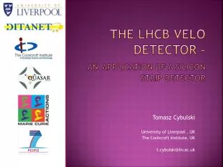
The Vertex Detector of LHCb - VeLo Aldo F. Saavedra Glasgow University On behalf of the VeLo group
Outline: • The VeLo group. • Introduction to LHCb . • Design goals of the VeLo. • The VeLo Module • Readout Chain • VeLo Peformance • VeLo Commissioning • Conclusion.
The VeLo group • Heidelberg University, Germany • MPI Heidelberg, Germany. • NIKHEF/Free University, The Netherlands. • CERN, Switzerland. • EPFL, Switzerland. • Glasgow University, UK. • Liverpool University, UK • Syracuse University, USA.
VeLo LHCb • Dedicated b-physics experiment at LHC • 1012 bb-pairs per year • CP violation and rare b-decays • Correlated boost of the bb-pairs • Single forward spectrometer
dIP = 14mm+35mm/pT Impact parameter resolution VeLo design goals • Primary vertex resolution of 8m for the x and y direction and 44m for z. • Provide tracking – On average each track will have 13 VeLo hits. One event expected to have 72 tracks. • 40fs proper time resolution. Measurement of BS oscillations • Part of the 2nd level trigger. A fast offline algorithm using the R z information finds displaced tracks.
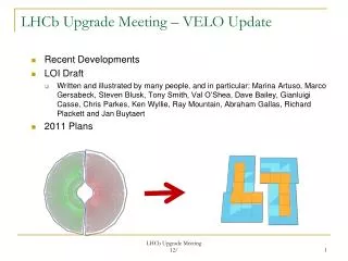
2 x “module halves” right half left half ~1m The VeLo Detector 1 x vacuum vessel 42 x sets of kapton cables 2 x “rf boxes” 42 x modules
The VeLo Module R-measuring sensor (concentric strips) 42 mm 8 mm Phi–measuring sensor (radial strips with an stereo angle) FE chip • Each module consists of two hybrids back to back. • The sensor is a 300μm silicon thick n+ in n-bulk. • Each hybrids posses either a R or Phi measuring sensor. • Pitch changes as a function of radius (40 – 100 μm). • Possess 2048 micro strips Production sensors are tested under vacuum: Individual sensors require a breakdown voltage greater than 350V and a current of a few μA. • The geometry and position of the VeLo results in non-uniform irradiation: • 1.3 * 1014 neq/cm2/year at R = 8 mm • 5 * 1012 neq/cm2/yearat R = 42 mm
Each hybrid has 16 Beetle v1.5 front end chip. A total of 1344 chips are required for the complete VeLo. • The Beetle chip has 128 channels. Each consists of a low noise charge sensitive pre-amplifiers, an active CR-RC pulse shaper and a buffer. • Fabricated on deep submicron (0.25μm) technology, thin gate oxide (~0.62Å) and enclosed NMO gates • Total doseradiation hardness > 130MRads • Triple-redundant logic ensures a robustness against Single Event Upsets (SEU) The VeLo Module • The VeLo the chips is operated in analogue mode: • The output of each channel is proportional to the charge deposited on the sensor. • This maximises the resolution of the position of clusters.
Peak Time Peak Pulse Height 25ns Remainder Undershoot Rise Time Response Time Undershoot Time Mean Operating Current Group 1 cut set at 2.2 sigma Yields 2092 chips out of 5000 (250 ± 8)mA Group 2 cut set at 3.5 sigma The VeLo Module The chip selection for VeLo production was based on the data gathered during the wafer probing performed at Heidelberg. The different analogue parameters measured • The probing measured: • Currents and register integrity. • Digital performance • Analogue performance of pre-amplifier and pipeline. • Cuts were applied to 69 variables in a bid to select a uniform batch of chips. • Variables were seperated in two groups. • 1st group of 18, most important, included: • currents, gain of pipeline cells, pulse variables such as Remainder/PH, Pulse Rise Time, • 2nd group of 51 included: • Gradient of registers, header amplitudes and cross talk etc.
ODIN TTC Phase sampling Gb eth. optical CCPC Computing Farm Analog Data cables 60m After delays are adjusted TELL1 TTCrx Ethernet (data) Switch Gb eth. CCPC x6 PVSS Repeater Boards Long Kaptons 6 Control Board Buff Buff 20m TTCrx ECS LV • Two quarters of the channels • are 5ns too slow • Test pulse is not centred. SPECS Buff Buff SPECS 16 Repeater power Temperature Board ISEG HV Ethernet (control) USB-CAN Temperature interlock CAN ELMB The Readout Chain 100kRads 500Rads PVSS 500Rads
Resolution Vs Projected Angle Resolution vs Pitch All Clusters (RMS) Pitch: 40μm Binaryresolution Pitch: 50μm Pitch: 60μm ’04 testbeam Pitch: 70μm Pitch: 80μm Pitch: 90μm Simulation Tuning Pitch: 100μm Hamamatsu sensor resolution Cluster efficiency vs. S/N cut Noise occupancy vs. S/N cut Performance of the VeLo Module Results test beam November 2004 – 300 μm thick Φ measuring sensor
VeLo Commissioning • The commissioning of the VeLo detector is a three step program before the final commissioning which will take place at the pit. They are fondly referred to as ACDCs. (Alignment Challenge / Detector Commissioning) • Two steps has involve a testbeam at the North Area testbeam facility at CERN. • As final components are available, the thoroughness of the commissioning increases. It involves hardware and software components. • In July 2006 part of the DAQ was commission. • In August 2006 ACDC 2 involved 3 production modules and readout electronics. • In November 2006 ACDC 3 will test the right half of the VeLo with 16 production modules and off detector electronics.
ACDC 2 TEST BOX CUSTOM REPEATER MECHANICS & INTERCONNECTS FINAL LONG KAPTONS ROTATING TABLE REPEATERS FULLY EQUIPPED WITH ECS, LV
X and Y Residuals before alignment Sigma = 42μm Sigma = 24μm X and Y Residuals after alignment Sigma = 15μm Sigma = 20μm Preliminary Results (ACDC2) • The algorithm developed is based on Millepede. • Mean value after alignment is close to zero, as expected, the code is doing his job… • Silicon to silicon misalignment not taken into account. The first ‘real’ VeLo alignment:
Conclusion • The VeLo is a key component of the LHCb Experiment. • Its design goals are expected to be met by the current implementation. • The VeLo module production is in full swing. Four modules a week are delivered to CERN for assembly. • First half to be installed in the pit in February 2007 with the second half to follow 2 months later. • The third ACDC will start on 6th of November and will be a dress rehearsal for the commissioning of the detector in the pit.
Factor1 = 2.2 Factor2 = 3.5 Yields 2092 chips (Total sample 5092) Back up slides A contour map of the yield as a faction of yield factor 1 and 2. The total number of Fes is 5012. Each yield factor was stepped from 1.80 to 4.10 using of 0.1 steps
Mean Reset Current (103 ± 5)mA
A typical event has 72 tracks On average Velo contains 13 hits, 3 TT , 11 IT 22 Outer Different version of Beetle chips.. The difference? Gain What is the average angle of the tracks