Download
1 / 7
80 likes | 118 Views
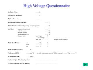
In three single phase high voltage underground cable induce voltages and currents in their sheaths. The sheath induced currents are undesirable and generate power losses and reduce the cable ampacity whereas the induced voltages can generate electric shocks to the workers that keep the power line. This means that when dealing with three single phase high voltage underground cable, it is very important to know the sheath currents called circulating currents that can circulate throughout the sheath and sheath voltage of the cables. It is very useful to know their values and the technique to reduce the sheath voltage of the high voltage Cable. This study presents as technique known as Mixed bonding technique combination of cross bonding and single point bonding to reduce the sheath voltage of the long length cable route. Manish Kumar | Ameen Uddin Ahmad "Mixed Bonding Method of High Voltage Cable" Published in International Journal of Trend in Scientific Research and Development (ijtsrd), ISSN: 2456-6470, Volume-1 | Issue-5 , August 2017, URL: https://www.ijtsrd.com/papers/ijtsrd2348.pdf Paper URL: http://www.ijtsrd.com/engineering/electrical-engineering/2348/mixed-bonding-method-of-high-voltage-cable/manish-kumar<br>

E N D
International Research UGC Approved International Open Access Journal UGC Approved International Open Access Journal Mixed Bonding Method of High Voltage Cable International Journal of Trend in Scientific Research and Development (IJTSRD) UGC Approved International Open Access Journal Scientific (IJTSRD) ISSN No: 2456 ISSN No: 2456 - 6470 | www.ijtsrd.com | Volume Volume - 1 | Issue – 5 Mixed Bonding Method of High Voltage Cable Manish Kumar M.Tech, Power System, Student, Department of Electrical & Electronics Engineering, AL- Falah University, Faridabad, Haryana, India Ameen Uddin Ahmad Ameen Uddin Ahmad Department of Electrical & AL-Falah University, Faridabad, Haryana, India M.Tech, Power System, Student, Department of Electrical & Electronics Engineering, Falah University, Faridabad, Haryana, India Assistant Professor, Department of Electrical & Electronic Engineering, AL Faridabad, Haryana, India underground or underwater. This is in contrast to an overhead line, which does not have insulation. High voltage cables of differing types have a variety of applications in instruments, ignition systems, and AC and DC power transmission. In all applications, the insulation of the cable must not deteriorate due to the high voltage stress, ozone produced by electric discharges in air, or tracking. The cable system mu prevent contact of the high voltage conductor with other objects or persons and must contain and control leakage current. Cable joints and terminals must be designed to control the high-voltage stress to prevent breakdown of the insulation. Often a high cable will have a metallic sheath layer over the insulation, connected to the ground and designed to equalize the dielectric stress on the insulation layer. High voltage cables have the structural elements of more conductors, insulation and a pro High voltage cables differ from lower voltage cables in that they have additional internal layers in the insulation jacket to control the electric field around the conductor. 1.1 Power Loss in High Voltage Cable An underground cable consists of three main components namely the materials, and sheath. When the cable is energized by a voltage, electric current will flow and will heat the a voltage, electric current will flow and will heat the ABSTRACT underground or underwater. This is in contrast to which does not have insulation. In three single phase high voltage underground cable induce voltages and currents in their sheaths. The sheath induced currents are undesirable and generate power losses and reduce the cable ampacity whereas the induced voltages can generate electric shock the workers that keep the power line. This means that when dealing with three single phase high voltage underground cable, it is very important to know the sheath currents called circulating currents that can circulate throughout the sheath and sheath the cables. It is very useful to know their values and the technique to reduce the sheath voltage of the high voltage Cable. This study presents as technique known as Mixed bonding technique combination of cross bonding and single point bonding sheath voltage of the long length cable route. Keyword: Sheath Voltage, Circulating Current, Bonding, High voltage, sheath voltage limite I. INTRODUCTION 1. High Voltage A high voltage cable used for electric power transmission at high voltage. A cable includes a conductor and insulation and is suitable for being run In three single phase high voltage underground cable induce voltages and currents in their sheaths. The sheath induced currents are undesirable and generate power losses and reduce the cable ampacity whereas the induced voltages can generate electric shocks to the workers that keep the power line. This means that when dealing with three single phase high voltage underground cable, it is very important to know the sheath currents called circulating currents that can circulate throughout the sheath and sheath voltage of the cables. It is very useful to know their values and the technique to reduce the sheath voltage of the high This study presents as technique known as Mixed bonding technique combination of cross bonding and single point bonding to reduce the sheath voltage of the long length cable route. High voltage cables of differing types have a variety cations in instruments, ignition systems, and power transmission. In all applications, the insulation of the cable must not deteriorate due to the high voltage stress, ozone produced by electric discharges in air, or tracking. The cable system must prevent contact of the high voltage conductor with other objects or persons and must contain and control leakage current. Cable joints and terminals must be voltage stress to prevent breakdown of the insulation. Often a high voltage cable will have a metallic sheath layer over the insulation, connected to the ground and designed to equalize the dielectric stress on the insulation layer. igh voltage cables have the structural elements of more conductors, insulation and a protective jacket. High voltage cables differ from lower voltage cables in that they have additional internal layers in the insulation jacket to control the electric field around Sheath Voltage, Circulating Current, Bonding, High voltage, sheath voltage limiter High Voltage Cable electric power A cable includes a An underground cable consists of three main components namely the materials, and sheath. When the cable is energized by conductor, conductor, dielectric dielectric conductor and insulation and is suitable for being run @ IJTSRD | Available Online @ www.ijtsrd.com @ IJTSRD | Available Online @ www.ijtsrd.com | Volume – 1 | Issue – 5 | July-Aug 2017 Aug 2017 Page: 564
International Journal of Trend in Scientific Research and Development (IJTSRD) ISSN: 2456-6470 cable. The temperature rise of a cable depends upon the rate of generation and dissipation of heat by the body. Thermal effects that occurred will result in losses. The losses are conductor losses, dielectric losses and sheath losses. Power loss in the cable can occur due to a variety of reasons. They may be caused by the conductor current passing through the resistance of the conductor (also sometimes called the copper loss on account of the fact that conductors were mainly made out of copper), dielectric losses caused by the voltage across the insulation, sheath losses caused by the induced currents in the sheath, and inter sheath losses caused by circulating currents in loops formed between sheaths of different phases. The dielectric loss is voltage dependant, while the rest is current dependant. In single core cables unlike three core cables, whenever current is passed in three phase ac system, it starts behaving like a single phase step down transformer. The conductor acts as a primary winding and metallic sheath of cables acts as secondary winding. Magnetic flux generated by the current flowing through the conductor induces an EMF in the cable metallic sheath circuit. The magnitude of EMF induced in the cable sheath is directly proportional to the magnitude of the current through conductor and the magnitude of mutual inductance between sheaths of the cables which depends upon the spacing between cables, cable diameter and length of the circuit. Spacing between different cores of cable depends upon how the cable has been laid down in trenches i.e. in trefoil formation or flat formation. Voltage induced in the sheaths of the cables is given by the formula E α ‘I ??’ Volts/m Where ‘I’ is current in the conductor and ‘??’ is the mutual inductance reactance between the cable sheaths. As the inter spacing between single core cables in flat formation is always more as compared to trefoil formation, hence voltage induced is also higher. The voltage induced between the sheaths of each cable is opposite in magnitude which causes circulating current to flow in the sheath when both ends of metallic sheaths are bonded to the ground. Sheath circulating current cause power loss and heating due to which cables are required to be de- rated. In order to utilize full capacity of the cable, special sheath bonding methods are employed. 2. Sheath Bonding Method of HV Cable 2.1. Single Point Bonding For single-end bonding, only one end of the cable sheath is connected to the earth while the other end is left floating. The voltage is induced linearly along the whole cable length and at the “open end” a standing voltage occurs. Generally, standing voltage is not of much concern except that if the runs are long and conductor current are high. As per IS 3043, the standing voltage should not exceed 65V. The open end should be protected with a sheath voltage limiter (SVL). This diminishes the chance of overvoltage occurring inside the cable screen, protects the cable system and ensures that relevant safety requirements are upheld. Fig 1: Single Point bonding The advantage of single-end bonding is that losses caused by circulating currents cannot occur. Another advantage is that one end is firmly grounded. The disadvantage of single-end bonding is the voltage which occurs at one end of the termination. This method is typically used for high voltage systems with a length of up to 1 km. 2.2 Midpoint Bonding Midpoint bonding is applied to cable systems with one joint in the middle of the system. In this bonding method the cable sheath is connected in the joint by @ IJTSRD | Available Online @ www.ijtsrd.com | Volume – 1 | Issue – 5 | July-Aug 2017 Page: 565
International Journal of Trend in Scientific Research and Development (IJTSRD) ISSN: 2456-6470 means of a straight through version with a grounding connection, which is directly connected to the earth. Fig 2: Mid Point bonding The advantage of mid-point bonding is that losses caused by circulating currents cannot occur. The disadvantage of mid-point bonding is the voltage that occurs at both end of the termination. The “open end” should be protected with an SVL. This diminishes the chance of overvoltage occurring inside the cable sheath, protects the cable system and ensures that relevant safety requirements are upheld. Midpoint bonding is used for cable systems with one joint up to a length of approximately 2 km. 2.3 Double Point Bonding System Double point bonding system (Both end bonding system) is the most Simple and Common method. In this sheath bonding method cable screen is bonded to earth grids at both ends via link box. To eliminate the induced voltages in cable sheath is to earth, the sheath at both ends of the cable circuit. This eliminates the need for the parallel continuity conductor used in single bonding systems. It also eliminates the need to provide SVL, such as that used at the free end of single point bonding cable circuits. Cable Suitable for route length of more than 500 Meter. Fig 3: Double Point bonding 2.4 Cross Bonding Cross-bonding is necessary for long cable segments with many joints. The cross-bonding system consists of three sections. In an ideal cross-bonding system, the three sections are of equal length. Fig 4: Cross bonding The advantage of cross-bonding is the absence of residual voltages at the end of the three sections. With no driving voltages, the sheath currents and therefore the losses in the system are zero. In reality, some minor differences between each section and a low current flow in the sheath do actually cause some losses. However, with a good cross-bonding system, the sheath losses can be kept very low. Another advantage of regular cross-bonding is that at the grounded termination ends the voltage is zero. @ IJTSRD | Available Online @ www.ijtsrd.com | Volume – 1 | Issue – 5 | July-Aug 2017 Page: 566
International Journal of Trend in Scientific Research and Development (IJTSRD) ISSN: 2456-6470 same must be true for cables b1 and b2 and c1 and c2. d)The spacing between three cables laid in one plane should be not less than the cable diameter. When the cables are arranged in a duct or on a rack in this way, each one should be secured either to be base or to the others by non-magnetic, non- corrosive clamps every 0·5 to 0·8m. e)Cables can also be laid in trefoil arrangement in ducts or on racks which improves current distribution and reduces sheath losses. f)If several single core cables are laid per phase, these should be arranged as follows to ensure balanced current distribution. Conductor current are shown by: I?= - ? I?= I? (1+ j0) (assigned to cable 2 and 5) I? = - ? Open circuit voltage on sheath to neutral are calculated by using below equations E??= I?. jX?? + I?.jX?? + I?.jX?? E??= I?. jX?? + I?.jX?? + I?.jX?? E??= I?. jX?? + I?.jX?? + I?.jX?? Where, X??=k log? ? ??? ? ??? X??=k log? ? ??? ? ??? X??=k log? ? ??? ? ??? And where, K is a constant = 2×ω×10?? = 1.257×f×10?? S??? is distance from cable 1 to cable 2 (meters) S??? is the distance from cable 2 to cable 3 (meters) S??? is the distance from cable 1 to cable 3 (meters) S??? is the distance from cable 1 to cable 4 (meters) S??? is the distance from cable 2 to cable 5 (meters) S??? is the distance from cable 3 to cable 6 (meters) S??? is the distance from cable 1 to cable 5 (meters) S??? is the distance from cable 3 to cable 5 (meters) S???is the distance from cable 1 to cable 6 (meters) r??is the mean sheath radius (meters) 3. Mixed Bonding In a three single phase alternated current, the system formed by the sheath is behave as a secondary circuit strongly linked to the primary circuit formed by the main conductors. Thus during the normal operation of phase cables it may appear considerable intense current flowing at the sheath that generate additional losses. The different conventional technique of the sheath bonding for high voltage cable are used such as single point bonding, both ends bonding, Cross bonding. This convectional technique of sheath bonding have certain limitation due to which it’s not feasible to apply this bonding technique to all practical system. The Single point bonding with Sheath voltage limiter in used for route length less than 1 km. Mid-point bonding is used for route length less than 2 km. Both ends bonding method is used for route length more than 500 m and that it provides path for circulating current. Heating effects in cable sheath, losses in cable. Cross bonding method is mainly used for long route length. Cross bonding bonding is reliable method and but for cross bonding method minor section length of approximately equal is required. Cross bonding technique there is also a limitation of equal minor section. As is real scenario and fast developing system, the route limit is long and complicated hence to limit the sheath voltage of high voltage cable, the best alternate is mixed bonding technique. Mixed bonding method is used for long route length when the number of minor sections is not exactly approximately divisible by three, the system can consist of different combination such cross bonding with single-point bonding or with double point bonding to limit the Sheath voltage level. 3.1 Calculation of Double-Circuit Systems The configuration of the double circuit system of high voltage cable. a)Six cables are connected in three phase circuits. b)All conductor currents are equal in magnitude. c)For six cables—point or line symmetry is assumed. This means a line a point 0 can be placed between the two circuits so that the distance from cable a1 to 0 equals the distance from cable a2 to 0, where a1 is the a phase of Circuit 1 and a2 is the a phase of Circuit 2. The ? + j√? ? (assigned to cable 1 and 4) ? - j√? ? (assigned to cable 3 and 6) ? ??? ? ??? X??=k log? ? ??? ? ??? X??=k log? ? ??? ? ??? X??=k log? @ IJTSRD | Available Online @ www.ijtsrd.com | Volume – 1 | Issue – 5 | July-Aug 2017 Page: 567
International Journal of Trend in Scientific Research and Development (IJTSRD) ISSN: 2456-6470 Calculation of Mixed bonding for double circuit The route lenth of cable is 4.9km + Ic. jXcc 35.27 V/km Phase Ec0 Induced complete length of cable in R phase Induced Voltage complete length of cable in Y phase Induced Voltage complete length of cable in B phase 156.382 V Voltage for 140.293 V for 172.806 V for Fig 5: Trefoil arrangement of double circuit Sheath Induced Voltage Calculation on Full load Ia, Ib Ic f Frequency K Constant (1.257*10- 6*f) D Geometric Mean Sheath Diameter rsm Mean sheath radius S12 Distance Cable 1- 2 S13 Distance Cable 1-3 S14 Distance Cable 1-4 S15 Distance Cable 1-5 S16 Distance Cable 1-6 S23 Distance Cable 2-3 S25 Distance Cable 2-5 S35 Distance Cable 3-5 S36 Distance Cable 3-6 Xaa k. Ln(1/(rsm*S14)) Xab k. Ln(1/(S12*S15)) Xac k. Ln(1/(S13*S16)) Xbb k. Ln(1/(rsm*S25)) Xbc k. Ln(1/(S23*S35)) Xcc k. Ln(1/(rsm*S36)) Load Current In Amps 575 A 50 0.00006285 Hz 71 Mm 0.036 0.085 0.085 0.700 0.746 0.662 0.085 0.785 0.700 0.615 0.00023 0.00017 0.00018 0.00023 0.00018 0.00024 M M M M M M M M M M M M M M M M Fig 6: Mixed Bonding Method Open Circuit Voltages on Sheath to Neutral on full load R- Phase Ea0 Y- Phase Eb0 B - Ia. jXac + Ib. jXbc 0.03527 Ia. jXaa + Ib. jXab + Ic. jXac 0.03191 31.91 V/m V/km Ia. jXab + Ib. jXbb + Ic. jXbc 0.02863 28.63 V/m V/km V/m @ IJTSRD | Available Online @ www.ijtsrd.com | Volume – 1 | Issue – 5 | July-Aug 2017 Page: 568
International Journal of Trend in Scientific Research and Development (IJTSRD) ISSN: 2456-6470 In mixed bonding method, the system consists of a combination of two cross-bonding and two single- points bonding as shown. Name Destina- tion Config ur- ation T-1 T-1/ Source Side to Earth L-2 Link-2 SVL This bonding is reliable method and but for cross bonding method minor approximately equal. Cross bonding technique there is limitation of equal minor section. As is real scenario and fast developing system the route limit is long and complicated hence to limit the Sheath voltage of High voltage cable the best alternate is mixed bonding technique. Mixed bonding method is used for long route length when the number of minor sections is not exactly approximately divisible by three. The Mixed bonding method is practical effective method to reduce the sheath voltage of the high voltage cable, reduce the sheath loss and heat loss. Hence Improved the life of the high voltage cable and Improve the amapacity of cable. Mixed bonding method will be economical and feasible method for long distance distribution and transimmison by high voltage cable. ACKNOWLEDGEMENT There is always a sense of gratitude which one expresses to other for the help and timely services they render during all phases of life. I too would like to do it as I really wish to express my gratitude towards all those who have been helpful to me. I am thankful to assistant professor Ameen Uddin Ahmad (Electrical & dissertation Supervisor) for providing me the opportunity to prepare a project in power system. REFERENCES [1] ANSI/IEEE Std 575-2014, IEEE Guide for Bonding Shields and Sheaths of Single-Conductor Power Cables Rated 5 kV through 500 kV. [2] LI, Zhonglei, DU, B. X., WANG, L., YANG, C., LIU, H. J.: The calculation of circulating current for the single-core cables in smart grid. Innov. Smart Grid Technologies, ISGT, Asia, 21–24 May, 2012. [3] CIGRE, Working group B1.18, Special bonding of high voltage power cables, October 2005. [4] IEC 60840:2011 Power cables with extruded insulation and their accessories for rated voltages above 30 kV (Um = 36 kV) up to 150 kV (Um= 170 kV) - Test methods and requirements. [5] J.S. Barrett, G.J.Anders. “Circulating current and hysteresis losses in screens, sheaths and armour of section length are SVL Direct Cross Bonding-1 Link-3 SVL L-3 Link-4 Direct to Earth SVL Cross Bonding-2 L-4 Link-5 L-5 Link-6 SVL L-6 Link-7 Direct to Earth SVL L-7 Single point -1 Link-8A L-8 Single point -2 Link-8B Direct to Earth SVL L-8 T-2 Receivin g End T-2 Electronic Engineering, Table:1 4. CONCLUSIONS In a three single phase alternated current, the system formed by the sheath is behave as a secondary circuit strongly linked to the primary circuit formed by the main conductors. Thus, during the normal operation of phase cables, it may appear considerable intense currents flowing at the sheath that generate additional losses. The different conventional technique of the sheath bonding of high voltage cable are used such as single point bonding, both ends bonding, Cross bonding. This convectional technique of sheath bonding have certain limitation due to which it’s not feasible to apply this bonding technique to all practical system. The Single point bonding with Sheath voltage limiter in used only for route length less than 1 km. Mid-point bonding is used for route length less than 2 Km. Both ends bonding method is used for route length more than 500 m. Cross-bonding method is mainly used for long route length method. @ IJTSRD | Available Online @ www.ijtsrd.com | Volume – 1 | Issue – 5 | July-Aug 2017 Page: 569
International Journal of Trend in Scientific Research and Development (IJTSRD) ISSN: 2456-6470 electric power cables-mathematical models and comparison with IEC Standard 287”. IEEE Proc.-Sei. Meas. Technol., Vol. 144, No. 3, pp. 101-110, May1997 [6] IS 3043 (1987): Code of practice for earthing [ETD 20: Electrical Installation]. [7] IEC Standard 60287, 'Calculation of the Continuous Current Rating of Cables (100% load factor)' 2nd edition 2001. [8] TZIOUVARAS, D. A.: Protection of high-voltage AC cables. Power Systems Conference: Advanced Metering, Protection, Control, Communication and Distributed Resources PS '06, pp. 316–328, 2006. [9] Anders, G.J., 'Rating Of Electric Power Cables In Unfavorable Thermal Environment', John Wiley & Sons, Inc. 2005 [10] P. L. Ostermann, Transmission Systems Reference Book, New York: Electric Power Research Institute, 1992 Edition, p. 9. [11] Central Cable Bhd. Batu Berendam, Melaka, XLPE Insulated Power Cable – JKR Specification Editor, Underground @ IJTSRD | Available Online @ www.ijtsrd.com | Volume – 1 | Issue – 5 | July-Aug 2017 Page: 570