Download
1 / 5
50 likes | 91 Views
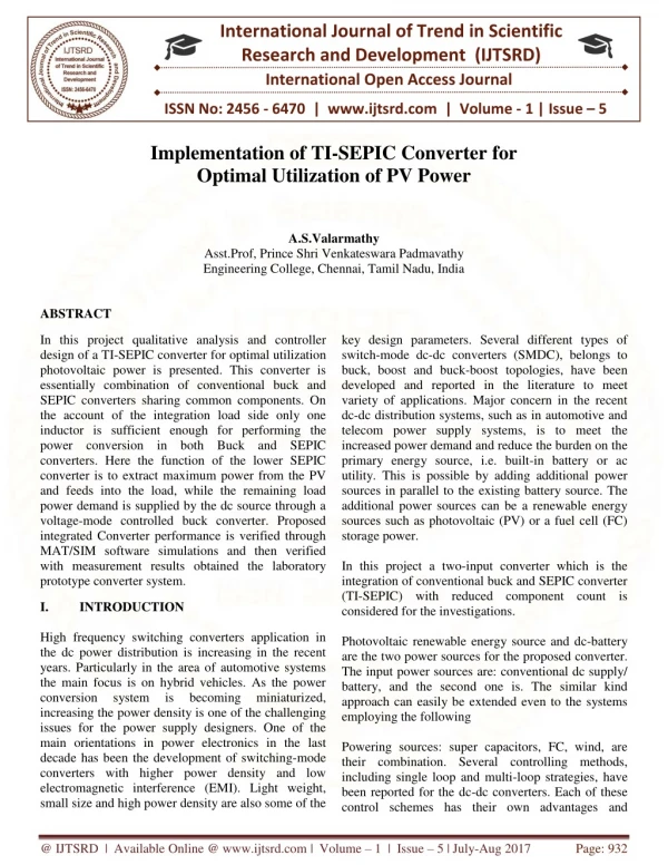
In this project qualitative analysis and controller design of a TI SEPIC converter for optimal utilization photovoltaic power is presented. This converter is essentially combination of conventional buck and SEPIC converters sharing common components. On the account of the integration load side only one inductor is sufficient enough for performing the power conversion in both Buck and SEPIC converters. Here the function of the lower SEPIC converter is to extract maximum power from the PV and feeds into the load, while the remaining load power demand is supplied by the dc source through a voltage mode controlled buck converter. Proposed integrated Converter performance is verified through MAT SIM software simulations and then verified with measurement results obtained the laboratory prototype converter system. A.S.Valarmathy "Implementation of TI-SEPIC Converter for Optimal Utilization Of PV Power" Published in International Journal of Trend in Scientific Research and Development (ijtsrd), ISSN: 2456-6470, Volume-1 | Issue-5 , August 2017, URL: https://www.ijtsrd.com/papers/ijtsrd2393.pdf Paper URL: http://www.ijtsrd.com/engineering/electrical-engineering/2393/implementation-of-ti-sepic-converter-for-optimal-utilization-of-pv-power/asvalarmathy<br>

E N D
International Journal of Trend in Scientific Research and Development (IJTSRD) International Open Access Journal ISSN No: 2456 - 6470 | www.ijtsrd.com | Volume - 1 | Issue – 5 Implementation of TI-SEPIC Converter for Optimal Utilization of PV Power A.S.Valarmathy Asst.Prof, Prince Shri Venkateswara Padmavathy Engineering College, Chennai, Tamil Nadu, India ABSTRACT In this project qualitative analysis and controller design of a TI-SEPIC converter for optimal utilization photovoltaic power is presented. This converter is essentially combination of conventional buck and SEPIC converters sharing common components. On the account of the integration load side only one inductor is sufficient enough for performing the power conversion in both Buck and SEPIC converters. Here the function of the lower SEPIC converter is to extract maximum power from the PV and feeds into the load, while the remaining load power demand is supplied by the dc source through a voltage-mode controlled buck converter. Proposed integrated Converter performance is verified through MAT/SIM software simulations and then verified with measurement results obtained the laboratory prototype converter system. key design parameters. Several different types of switch-mode dc-dc converters (SMDC), belongs to buck, boost and buck-boost topologies, have been developed and reported in the literature to meet variety of applications. Major concern in the recent dc-dc distribution systems, such as in automotive and telecom power supply systems, is to meet the increased power demand and reduce the burden on the primary energy source, i.e. built-in battery or ac utility. This is possible by adding additional power sources in parallel to the existing battery source. The additional power sources can be a renewable energy sources such as photovoltaic (PV) or a fuel cell (FC) storage power. In this project a two-input converter which is the integration of conventional buck and SEPIC converter (TI-SEPIC) with reduced component count is considered for the investigations. Photovoltaic renewable energy source and dc-battery are the two power sources for the proposed converter. The input power sources are: conventional dc supply/ battery, and the second one is. The similar kind approach can easily be extended even to the systems employing the following Powering sources: super capacitors, FC, wind, are their combination. Several controlling methods, including single loop and multi-loop strategies, have been reported for the dc-dc converters. Each of these control schemes has their own advantages and I. High frequency switching converters application in the dc power distribution is increasing in the recent years. Particularly in the area of automotive systems the main focus is on hybrid vehicles. As the power conversion system is increasing the power density is one of the challenging issues for the power supply designers. One of the main orientations in power electronics in the last decade has been the development of switching-mode converters with higher power density and low electromagnetic interference (EMI). Light weight, small size and high power density are also some of the INTRODUCTION becoming miniaturized, @ IJTSRD | Available Online @ www.ijtsrd.com | Volume – 1 | Issue – 5 | July-Aug 2017 Page: 932
International Journal of Trend in Scientific Research and Development (IJTSRD) ISSN: 2456-6470 limitations. In this paper a simple and cost effective single-loop voltage-mode controller is designed for the buck converter, while perturb and observation technique is employed for the maximum power point (MPP) tracking of the TI-SEPIC. II. BLOCK DIAGRAM Fig 3.1, the circuit diagram of proposed system is shown. The diode ‘D2’ is common to both the converters, while the individual converters are having their own switching devices. Load and its filtering capacitor are common to both the converters. Hence the filtering requirement is less as compared to the individual converter connecting in parallel. The buck converter is formed by: S1, D1, L1, R, while the SEPIC converter is formed by: S2, D2, L1, L2, C2, R. Depending on the location of the PV renewable energy source and dc-battery in the two input converter, there are two different power conversion combinations are possible.The main advantage of this integrated topology over the integrated topologies parallel connection at the load terminals is that the order of the power conversion topology is less by one. In view of order reduction the dynamical behavior is somewhat simpler than when it is using two separate inductors. The circuit can actually operate either in continuous or discontinuous inductor current mode. But, its operation in a discontinuous mode of operation will not provide benefits for the power conversion, and also on the account of higher power demand the current flows in ‘L1’ for most loading conditions. Furthermore, ‘L2’ is designed such that current is continuous even at lower solar insolations. Here, the converter switching frequency must be chosen such that the current in ‘L2’ is continuous even at lower solar insolations. In view of this the circuit operation is discussed here only for continuous inductor current mode (CICM). IV. SIMULATION AND RESULT Fig. 1.1 Block diagram of Proposed System Fig 1.1, the block diagram of proposed system consists of Buck converter, SEPIC converter, DC input, solar input, inductance, filter, pulse generator PID controller and load. Here, the function of SEPIC converter is to extract power from the solar input and feed into load, while the remaining load power demand is supplied by the dc source through buck converter. DC input is given to the buck converter and solar input is given to the SEPIC converter. Buck and SEPIC converter is integrated by means of inductance. Because of this integration, only one inductor is sufficient enough on load side for performing the power conversion in both buck and SEPIC converter. Filter is used to remove the unwanted signals and harmonics. PID Controller will generate the triggering pulses. Resistive load is used. 4.1 Simulation block diagram and result for Open loop control 4.1.1 Simulation Block Diagram III. CIRCUT DIAGRAM Fig. 3.1 Circuit diagram of Proposed System @ IJTSRD | Available Online @ www.ijtsrd.com | Volume – 1 | Issue – 5 | July-Aug 2017 Page: 933
International Journal of Trend in Scientific Research and Development (IJTSRD) ISSN: 2456-6470 Fig 4.1 Simulink model for open loop control of Buck-integrated SEPIC converter 4.2.1 Simulation Block Diagram In open loop control, a 100V input voltage is given to Buck converter. Another 100V input voltage which represents the output voltage of PV module is given to the SEPIC converter. An output of 135.1V is obtained. The pulse for the switch in Buck and SEPIC converter is developed by the following equation. Where dc is the duty cycle of the switch S1 and dp is the duty cycle of switch S2. 4.1.2 Simulation Result Fig 4.3 Simulink model for closed loop control of Buck-integrated SEPIC converter 4.2.2PID controller for Buck-integrated SEPIC converter Fig 4.2 Simulation result for open loop control of Buck- integrated SEPIC converter Fig 4.4 PID controller 4.2 SIMULATION BLOCK DIAGRAM AND RESULT FOR CLOSED LOOP CONTROL Here also 100V input supply is given to Buck and SEPIC converter. An output of 135v is obtained. The pulse for the switch in Buck and SEPIC converter is developed by PID controller. Reference voltage in the PID controller is set as 135V. @ IJTSRD | Available Online @ www.ijtsrd.com | Volume – 1 | Issue – 5 | July-Aug 2017 Page: 934
International Journal of Trend in Scientific Research and Development (IJTSRD) ISSN: 2456-6470 4.2.3 Simulation Result Comparison of various Buck-Boost converters is shown in table 5.1. From that it is clear that SEPIC converter is more advantageous than others. Table 5.1 Comparison of Various Buck-Boost Converters CONCLUSION Buck- integrated SEPIC converter suitable for the PV applications was proposed. A simple and cost effective open loop and closed loop control is designed. PID controller is used for the closed loop control of buck-integrated SEPIC converter Proposed control scheme effectiveness was analysed and the following conclusions were drawn: (i) in all these cases the total load demand is met by the two sources, (ii) the SEPIC converter is capable of extracting PV power (iii) dc bus voltage regulation was achieved and (iv) load changes are reflecting on the fixed dc source connected through buck converter, while extracting the available power from the PV source, which ensures the effective utilization of the renewable source. Converter performance for the proposed integrated converter is analyzed through MATLAB software simulations. REFERENCES 1.Nicola M. Pearsall and Robert Hill, “Photovoltaic Modules, Systems Northumbria Photovoltaic Application Centre University, Apr 2001. 2.R.Sridhar, Dr.Jeevananathan, N.Thamizh Selvan and Saikat Banerjee “Modeling of PV Array and Performance Enhancement by MPPT Algorithm” International Journal Applications,Vol. 7, No.5, Sep 2010 3.Matsuo H., Kobayashi K., Sekine Y., Asano M.and Lin Wenzhong “Novel Solar Cell Power Supply System Using theMutip1e-Input D C -DC Converter” Telecommunications Conference, Oct 1998. Fig 4.5 Simulation result for closed loop control of Buck- integrated SEPIC converter V. BENEFITS OF SEPIC CONVERTER It can be operated in step up or step down mode. It doesn’t suffer from polarity reversal problem. It has low amount of EMI due to low input current ripple. SEPIC converter has high efficiency and non- pulsating input current. Nowadays, the use of a DC-DC converter is widespread in modern electronic equipment and system. When renewable energy source is used, the voltage can vary over a wide range. Hence to continue supplying a constant load voltage, the converter must be able to work in both buck and boost modes. The DC-DC converters that meet this operational requirement are Buck-boost, Cuk, and SEPIC converters. However, the Buck-boost and Cuk converters, in their basic form, produce the output voltage, whose polarity is reversed from the input voltage. The problem can be corrected by incorporating an isolation transformer into the circuits, but this will inevitably lead to the increased size and cost of the converters. On the other hands, the SEPIC (Single-Ended Converter) converter is capable of operating in both step-up and step-down modes and does not suffer from the polarity reversal problem. and Applications”, of Computer Primary Inductor Energy @ IJTSRD | Available Online @ www.ijtsrd.com | Volume – 1 | Issue – 5 | July-Aug 2017 Page: 935
International Journal of Trend in Scientific Research and Development (IJTSRD) ISSN: 2456-6470 4.Vuthchhay Eng., Unnat Pinsopon, and Chanin Bunlaksananusorn “Modeling of a SEPIC Converter Operating in Continuous Conduction Mode” Electrical Engineering/Electronics, Computer, Telecommunications and Information Technology, 6th International Conference on May 2009 5.Yaow-Ming Chen, Yuan-Chum Liu, and Sheng- Hsien Lin “Double-Input PWM DC/DC Converter for Highnow Voltage Sources” Industrial Electronics, IEEE Transactions on Oct 2003. 6.Bryan G. Dobbs and Patrick L. Chapman “A Multiple-Input DC-DC Converter Topology” IEEE Power Electronics Letters, Vol. 1, March 2003. 7.Hirofumi Matsuo, Wenzhong Lin, Fujio Kurokawa, Tetsuro Shigemizu, and Nobuya Watanabe “Characteristics of the Multiple-Input DC–DC Converter” IEEE Transactions On Industrial Electronics, Vol. 51, No. 3, June 2004. 8.Luca Solero, Alessandro Lidozzi and Josè Antenor Pomilio “Design of Multiple-Input Power Converter for Hybrid Vehicles” IEEE Transactions On Power Electronics,Vol. 20, No. 5, Sep 2005. 9.S. Yuvarajan, Dachuan Yu and Shanguang Xub “A novel power converter for photovoltaic applications” Journal of Power Sources 135 (2004) 327–331. 10.Michael D. Seeman, and Seth R. Sanders “Analysis and Optimization Capacitor DC–DC Converters” IEEE Transactions on Power Electronics, Vol.23, No. 2, March 2008. 11.Vuthchhay Eng., Unnat Pinsopon, and Chanin Bunlaksananusorn “Modeling of Converter Operating in Discontinuous Conduction Mode” Electrical Computer, Telecommunications and Information Technology, 6th International Conference on May 2009. 12.Ruichen Zhao and Alexis Kaminski “Multiple- input single ended primary inductor converter (SEPIC) Converter for Distributed Generation Applications” Energy Conversion Congress and Exposition, Nov 2009. 13.Gene F. Franklin, J. David Powell, Abbas Emami- Naeini. Feedback Control of Dynamic Systems. 3rd edition. USA. Addison-Wesley,1994 14.Ogata, K. (2002) Modern Control Engineering 4th edition. USA Prentice Hall. Switched- of a SEPIC Engineering/Electronics, @ IJTSRD | Available Online @ www.ijtsrd.com | Volume – 1 | Issue – 5 | July-Aug 2017 Page: 936