Download
1 / 7
70 likes | 94 Views
Due to cost pressure, device complexity and size issue, most of the digital communication receiver designers try to avoid very sharp Anti Aliasing filter. And because of that aliasing frequency e.g. image frequency e.g. ghost cell frequency appear inside the digital baseband, which apparently remained un noticed to the receiver. As receiver is blind about that signal so, it processes the aliasing signal frequency as a desired cell frequency and if the aliasing signal is strong enough, then the initial mobile receiver's operations like, cell search and camp on etc. will be successfully performed using that aliasing signal. Later, during the uplink transmission time the receiver will discover that it has wrongly camped to an aliasing frequency, as network will not respond to mobile receiver's message due to mismatch in DL and corresponding UL ARFCN.Here in this paper, a simple, fast and efficient method is proposed to detect the presence of aliasing frequency in the received digital baseband signal. First the dc power at 0 Hz is estimated using I and Q signal average, then that is compared with the dc power after rotating by p radian e.g. fs 2 half sampling frequency in case of a twice oversampled received signal . If the estimated dc power before rotation is much higher than the dc power after rotations that will indicate there is no aliasing frequency present in the received digital baseband signal. And in such case, the receiver will process further the received signal, otherwise it will discard or take the appropriate action to combat the aliasing. Dr. Om Prakash | Dr. Sajal Kumar Das | Dr. N. Rajesha "Aliasing Frequency Detection In a Communication Receiver " Published in International Journal of Trend in Scientific Research and Development (ijtsrd), ISSN: 2456-6470, Volume-1 | Issue-5 , August 2017, URL: https://www.ijtsrd.com/papers/ijtsrd2279.pdf Paper URL: http://www.ijtsrd.com/engineering/electronics-and-communication-engineering/2279/aliasing-frequency-detection-in-a-communication-receiver--/dr-om-prakash<br>

E N D
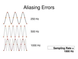
International Journal of Trend in Scientific Research and Development (IJTSRD) UGC Approved International Open Access Journal ISSN No: 2456 - 6470 | www.ijtsrd.com | Volume - 1 | Issue – 5 Aliasing Frequency Detection in a Communication Receiver Dr Om Prakash Professor, ECE Dept., MRIET, Secunderabad, Telangana, India Dr Sajal Kumar Das Ericsson R&D, Bangalore, KA, India Dr. N. Rajesha Associate Professor, ECE Dept., MRIET, Secunderabad, Telangana, India ABSTRACT Keywords:AA: Anti-Alias, DCR: Direct Conversion Receiver, RF: Radio Frequency, ADC: Analog to Digital Converter, WCDMA: Wideband Code Division Multiple Access, ARFCN: Absolute Radio- Frequency Channel Number, UL: Uplink, DL: Downlink, UE: User Equipment Due to cost pressure, device complexity and size issue, most of the digital communication receiver designers try to avoid very sharp Anti- Aliasing filter. And because of that aliasing frequency e.g. image frequency e.g. ghost cell frequency appear inside the digital baseband, which apparently remained un- noticed to the receiver. As receiver is blind about that signal so, it processes the aliasing signal frequency as a desired cell frequency and if the aliasing signal is strong enough, then the initial mobile receiver’s operations like, cell search and camp on etc. will be successfully performed using that aliasing signal. Later, during the uplink transmission time the receiver will discover that it has wrongly camped to an aliasing frequency, as network will not respond to mobile receiver’s message due to mismatch in DL and corresponding UL ARFCN. 1.INTRODUCTION Today due to cost, size and several other benefits [1], direct conversion RF receiver is most commonly used. This directly converts the RF frequency to base band (pass band) frequency, which is then low-pass filtered and sampled using ADC as shown in Fig-1. According to Nyquist - “Exact reconstruction baseband signal from its samples is possible, if the signal is band-limited and the sampling frequency is greater than twice the signal bandwidth.” An alias occurs when a signal above half the sample rate is allowed into, or created within, a digital system. If the sampling condition is not satisfied, then the original signal cannot be recovered without distortion and the frequencies will overlap. So, frequencies above half the sampling rate will be reconstructed as, and appear as, frequencies below half the sampling rate. As it is a duplicate of the input spectrum “folded” back on top of the desired spectrum that causes the distortion, this is why this type of sampling impairment is known as “foldover distortion” and the resulting distortion is also called aliasing. To prevent or reduce aliasing, two things are of a continuous-time Here in this paper, a simple, fast and efficient method is proposed to detect the presence of aliasing frequency in the received digital baseband signal. First the dc power at 0 Hz is estimated using I and Q signal average, then that is compared with the dc power after rotating by π radian (e.g. fs/2 – half sampling frequency in case of a twice oversampled received signal). If the estimated dc power before rotation is much higher than the dc power after rotations that will indicate there is no aliasing frequency present in the received digital baseband signal. And in such case, the receiver will process further the received signal; otherwise it will discard or take the appropriate action to combat the aliasing. @ IJTSRD | Available Online @ www.ijtsrd.com | Volume – 1 | Issue – 5 | July – August 2017 Page: 279
International Journal of Trend in Scientific Research and Development (IJTSRD) ISSN: 2456-6470 considered- (1) Increase the sampling rate more than or equal to twice the maximum signal frequency in that band (2) Introduce an anti-aliasing filter or make the anti- aliasing filter more stringent. Anti-aliasing (AA) filters remove any frequency components beyond one half of the Nyquist rate. However, AA filters may be rather complex filters that are difficult to design and integrate onto an integrated circuit. And difficult to design if the desired frequency response is sharp. Furthermore, these are bulky leading to more silicon real estate size and expensive. Moreover, AA filters are static in nature, meaning that their frequency response cannot be changed dynamically. So due to these issues, today, in most of the receiver systems the AA filters are not designed very sharp response (for example WCDMA filter roll off used is 0.22). That leads to the door for Aliasing. even after putting lot of anti-aliasing mechanisms) whether aliasing is present or not in the received signal. This is very important to know, because- if the alias frequency signal enters inside the baseband, then baseband will treat that as if it is the desired channel frequency signal. So, it will use that for normal receiver processing. That will lead to several critical issues. There as several such issues are reported from the field tests and published from other sources. Here, the main issue is that, the alias frequency signal leaks into the baseband with higher magnitude. During cell re-selection and RSSI measurement process, the receiver finds the alias frequency as one of the potential cell and goes ahead with cell search with that aliasing frequency. The cell search may be successful if the signal amplitude of that cell frequency (appearing as aliasing frequency) is much higher. RSSI algorithm will select that cell frequency as it has higher signal strength and after that it tries to do the cell search operations (3 steps WCDMA cell search), that also passes as the signal level was good for that aliasing frequency (also known as Ghost cell). That means primary scrambling code of the cell is identified and then BCH channel information is also read by the receiver. These operations take lot of time. At this stage UE thinks that it has camped to the desired best cell. But, when it tries to send the uplink message (transmission) that time the uplink frequency ARFCN corresponding to the downlink frequency (here detected aliasing frequency) ARFCN will be used by the MS, but that will not match with the network’s expectation of the uplink frequency. As the cell’s DL frequency was different from the camped aliasing frequency. So, there will be no response from the network. Eventually, UE can’t proceed after the initial cell selection. Due to that after spending so much of energy, resources and time- UE has to look for other cell. This causes several critical issues and degrades the performance. Fig-1, typical digital receiver with DCR RF down conversion architecture and Aliasing issue in Receiver 2.REVIEW OF EXISTING METHODS Aliasing is not a today’s problem; it exists since the digital era started. So, there are several Patents exists on aliasing removal US7103489 B2- “Active removal of aliasing frequencies in a decimating structure by changing a decimation ratio in time and space”. US 6804392 techniques like, Similarly there are several issues associated with the aliasing and various problems occur as a result of that. But if the receiver would have been able to detect the presence of aliasing frequency signal in the received signal using some method, then it would have – (a) prevented the receiver processing using that signal to avoid Ghost cell issue as described above, which would have helped to save time, B1- “Removing color aliasing artifacts from color digital images”. US 6492922 B1- “Anti-aliasing filter with automatic cutoff frequency adaptation”. But, either these are very complex methods or imposes methods for the AA filters improvement etc., but none of these can solve to identify (may be @ IJTSRD | Available Online @ www.ijtsrd.com | Volume – 1 | Issue – 5 | July – August 2017 Page: 280
International Journal of Trend in Scientific Research and Development (IJTSRD) ISSN: 2456-6470 Scenario 1: processing power and battery energy (b) or, it would have used some method to reduce the effect of aliasing for example sharp filtering etc. So, here, we propose one method which helps to detect the presence of aliasing signal in the received over sampled signal, which might be very useful in this scenarios to overcome these above discussed issues. 3.NOVEL METHOD OF ALIASING DETECTION ➢Objective The primary objective of this paper is to detect the presence of aliasing frequency signal in the received oversampled baseband signal. There arises a situation wherein presence of remnant aliasing frequency signal oversampled baseband signal post anti-aliasing filtering is strong enough to distort the intended desired signal. If it is possible to detect the presence of aliasing frequency signal, then receiver may take an appropriate action to remove the aliasing frequency signal, that is, either employ anti-aliasing filter with more stringent stop band attenuation or handles it some other way to overcome its negative effect. Hence, the main issue is to detect the presence of aliasing frequency signal in order to mitigate its deleterious effect. Figure-2, no desired signal frequency but only aliasing frequencies signal is present Scenario 2: in the received Figure-3: desired signal frequency and aliasing frequencies signal are present Scenario 3: ➢Possible scenarios There arise three possible scenarios due to the presence or absence of aliasing frequency signal and desired frequency signal in an oversampled received baseband signal. These possible scenarios are depicted below. Let us consider the received signal is 2x times over-sampled for the illustration purpose. Figure-4, only desired frequency signal is present In all three possible scenarios, today receiver is blind about the presence of residue aliasing frequencies signal in the received digital baseband as mentioned in section 2. The residue aliasing signal distorts desired used signal when the receiver does further receiver processing using 1x samples of over-sampled received signal (from 2x oversample data). @ IJTSRD | Available Online @ www.ijtsrd.com | Volume – 1 | Issue – 5 | July – August 2017 Page: 281
International Journal of Trend in Scientific Research and Development (IJTSRD) ISSN: 2456-6470 Though there are 2x over samples I, Q data is available in the receiver baseband but for many operations receiver does not use the over sampled I, Q data, rather it uses 1x samples for lesser processing overhead and hence lower power consumption. For example, the Cell Search and Path Search modules might use 1x samples instead of 2x samples, for reducing the processing overhead and power consumption overhead in UE. As 1x sample processing for these operations is good enough to achieve the required performance. But, that might lead to issues as described in section 2 and illustrated in figure 5 and 6 for scenarios A and B respectively. algorithm as described below using over sampling signal (2x) as input. ➢Aliasing detection algorithm Let’s consider that the oversampled received [I,Q] samples from the ADC in baseband are [I(n),Q(n)]. Then the following steps are performed: (a)Compute dc power before rotation: Mean value of I and Q are computed by adding the I(n) and Q(n) as: k N 1 k N 1 ………………………(1) Then, compute the dc power using the I,Q mean values from equation (1) as N 1 [ ] I I n mean Scenario A: Distortion of desired signal (there is no desired signal and aliasing signal appears as desired signal) N 1 [ ] mean Q Q n P(dc)_before_rotation = Imean2 + Qmean2….......(2) (b)Rotate the received [I(n),Q(n)] samples by e-jπn (digital domain) or e-jωt = e-j2.π(0.5*fs).t(analog domain). Where, fs is the sampling frequency. (c)Compute dc power after rotation: Rotate the I,Q samples by π amount: Now, after [I(n),Q(n)] samples rotation by π => [I(n),Q(n)] e- j2.π(0.5)fs.t, each rotated samples I’(n) and Q’(n) will be added up and mean value of I and Q is computed. k N 1 k N 1 …..…………………(3) Then, compute the dc power using the I,Q mean values from equation (3) as, P(dc)_after_rotation= I’mean2+ Q’mean2.…..(4) Now, we have two power values: original dc power (from equation-1) P(dc)_before_rotation , and dc power after π rotation (from equation-4) P(dc)_after_rotation. Next, the detection of the presence of aliasing frequency signal in the over-sampled received signal will be based on the hypothesis described in the next section. Figure-5, there is no desired signal and aliasing signal appears as desired signal Scenario B: Distortion of desired signal N 1 ' [ ' ] I I n mean N 1 ' [ ' ] Q Q n mean Figure-6, there is desired signal and aliasing signal and mixture of those appears as desired signal The receiver has received oversampled I, Q data (2x samples) from the RF module and performing different operations (like, Cell search and path search etc.) using 1x samples. An algorithm is proposed to detect the presence of aliasing frequency signal in the received over-sampled signal as mentioned below. The aliasing detection ➢Decision hypothesis for aliasing detection (a) If there was desired signal in the received @ IJTSRD | Available Online @ www.ijtsrd.com | Volume – 1 | Issue – 5 | July – August 2017 Page: 282
International Journal of Trend in Scientific Research and Development (IJTSRD) ISSN: 2456-6470 baseband digital signal and also alias frequencies were present, then after the π rotation (fs/2)- the rotated spectrum will look like as shown in figure-7. Fig-8, rotation of received baseband digital signal (when there is only desired signal and no aliasing signal frequency present) Fig-7, rotation of received baseband digital signal (when there is desired signal, and aliasing signal frequency both present) Decision Hypothesis-bI: P(dc)_before_rotation > threshold_2*P(dc)_after_rotation Decision Hypothesis-aI: In this case, the power at dc before rotation will be higher than after rotation indicating there is no presence of aliasing frequency signal and hence receiver can proceed further decoding the desired signal. (P(dc)_before_rotation (P(dc)_before_rotation > threshold_2*P(dc)_after_rotation) & > P(dc)_after_rotation) In this case, the power at dc before rotation will be higher than after rotation indicating weak aliasing frequency signals which can be ignored and hence receiver can proceed further decoding the desired signal. (c) If there was no desired signal in the received baseband digital signal and only alias frequencies were present, then after the π rotation (fs/2)- the rotated spectrum will look like as shown in figure-9. Decision Hypothesis-aII: (P(dc)_before_rotation (P(dc)_before_rotation < threshold_2*P(dc)_after_rotation) & > P(dc)_after_rotation) In this case, the power at dc before rotation will be greater than after rotation though not very high. This indicates that aliasing frequency signal is not weak and further receiver processing is required to remove it. Hence, the receiver can employ here one more anti- aliasing filtering to remove the effect of aliasing signal before proceeding to decode the desired signal. Figure-9, rotation of received baseband digital signal (when there is no desired signal, only aliasing signal frequency is present) Decision hypothesis-cI: Where, threshold_2 is a tunable parameter and which can be empirically derived to favour any particular hypothesis. (P(dc)_before_rotation (threshold_1*P(dc)_before_rotation < P(dc)_after_rotation) < P(dc)_after_rotatio) & Where, threshold_1 is a tunable parameter and which can be empirically derived. This is confirming further that the aliasing frequency signal is present positively. (b) If there was desired signal in the received baseband digital signal and no alias frequency was present, then after the π rotation (fs/2)- the rotated spectrum will look like as shown in figure-8. In the case the power at dc before rotation will be lower than after rotation. If that condition is satisfied then that indicates there is only aliasing frequency components are present in the received digital baseband signal. So, receiver may not use that @ IJTSRD | Available Online @ www.ijtsrd.com | Volume – 1 | Issue – 5 | July – August 2017 Page: 283
International Journal of Trend in Scientific Research and Development (IJTSRD) ISSN: 2456-6470 received signal for any processing, for example, the receiver may decide not to do the cell search operation as the aliasing signal will appear as a Ghost cell and receiver will be blind about the presence of that and will only be able to realize at the later stage as described in section 2. Start Receive analog RF signal, down-convert it, filter the down-converted signal using anti-aliasing filter and then over-sample it using ADC Compute mean value of I(n) and Q(n) from the received oversampled signal. Compute the DC power P(dc)_before_rotation = Imean 2 + Qmean 2 The detailed flow diagram of the proposed method for aliasing detection is shown in figure 10. Rotate the I(n) and Q(n) by pi. Compute mean value of rotated IQ samples I’(n) and Q’(n). Compute new rotated DC power P(dc)_after_rotation = I’mean Once the presence of aliasing frequency signal is detected in the received signal using this above method, then receiver can decide to employ different methods to overcome the aliasing effect (for example sharp filtering etc.) or it might decide not to use that received signal for receiver processing (for the reason as explained in section 2.2). 2 + Q’mean 2 weak aliasing frequency signals which can be ignored and receiver can proceed further decoding the desired signal. (P(dc)_before_rotation > P(dc)_after_rotation) & (P(dc)_before_rotation >= threshold_2*P(dc)_after_rotation) Yes No aliasing frequency signal is not weak and one more anti-aliasing filtering is necessary to remove the effect of aliasing signal before proceeding to decode the desired signal Yes (P(dc)_before_rotation > P(dc)_after_rotation) & (P(dc)_before_rotation < threshold_2*P(dc)_after_rotation) 4.MERITS OF THIS PROPOSED METHOD This proposed method provides several potential benefits as described below. No aliasing frequency signal is very strong compared to desired signal and one more anti-aliasing filtering is necessary to remove the effect of aliasing signal before proceeding to decode the desired signal Yes No Only aliasing signal is present and receiver can stop further processing. (P(dc)_before_rotation < P(dc)_after_rotation) & (threshold_1*P(dc)_before_rotation < P(dc)_after_rotation) (a)This is an easy method to detect the presence of aliasing frequency signal (image signal) in the received baseband digital desired signal. (b)Detection of unwanted aliasing frequency cell signal during the initial cell search operation will help to take appropriate action beforehand. That will save lot of processing power, battery power and delay in cell search by avoiding the last stage discovery of wrong cell. (c)Better and faster cell search due to avoidance of aliasing frequency or image frequency or Ghost cell processing. (d)Takes very minimal processing power to detect. (e)Can be applied in any digital communication systems for aliasing frequency signal detection and hence taking appropriate action if detected only (through sharp filter etc., leading to lower complexity and use whenever detected). Anti-aliasing filter Decode the received signal End Figure-10, decision flow diagram of the proposed algorithm 5.CONCLUSION If the receiver is not aware about the presence of aliasing frequency signal in the received baseband digital signal, then the receiver processes that unwanted or corrupted signal as desired signal and do all the baseband receiver processing. These unwanted processing cause lot of waste of processing resources and hence battery energy. This also causes a major issue of delay in mobile receiver’s cell search process and also in cell detection process due to camping on a wrong frequency. As mentioned in section 2, there could many problems associated with this aliasing frequency and receiver is blind about that. This is a severe problem and there are several issues reported in the past related to this. So, this solution will provide an easy detection of the presence of aliasing frequency in the received baseband signal and hence by detecting that it will @ IJTSRD | Available Online @ www.ijtsrd.com | Volume – 1 | Issue – 5 | July – August 2017 Page: 284
International Journal of Trend in Scientific Research and Development (IJTSRD) ISSN: 2456-6470 help receiver to take proper action on time, instead of wasting the time, resource and energy. REFERENCES 1)Sajal Kumar Das, “Mobile Handset Design”, JOHN WILEY & SONS, ISBN: 978-0470824672, April 2010. 2)Chi-Yuan Chen, Fan-Hsun Tseng, Kai-Di Chang, Han-Chieh Chao and Reconfigurable Software Defined Radio and Its Applications, Journal of Science and Engineering, Tamkang, Vol. 13, No. 1, pp. 29_38, 2010. 3)D. Gabor, “Theory of communication”, Journal of the Institute of Electrical Engineers, vol. 93, pp. 429-457, 1946. 4)A. Said, “A new class of filters for image interpolation and resizing”, Int. Conf. on Image Processing, vol. 4, pp. 217-220, 2007. Jiann-Liang Chen, @ IJTSRD | Available Online @ www.ijtsrd.com | Volume – 1 | Issue – 5 | July – August 2017 Page: 285