Download
1 / 5
50 likes | 78 Views
For an electronic product or chip if functional faults exist, then the product or chip is of no use. Therefore, if we take a cache memory, a secondary memory for high speed retrieval of data stored where functional faults exist. These functional faults in the data stored in the cache can be converted into performance faults so that the caches can still be marketable. In processors, caches are designed as Level 1 L1 , Level 2 L2 , and the least hard disk. If the processor wants the data from to memory it checks the availability of data in upper level cache L1 and if the data is found it sends to the processor. If the data is not found in L1, it checks in lower level cache L2 and next in L3 and at the least in slow memory or hard disk. So, in this process, many functional faults may exist which leads to making the processor faulty. So, to protect the cache memory ECC and BIST are used. For a cache redesign, a PDT cache is used where functional faults are converted into performance faults. We propose a new PDT way tagged cache design which leads to increased performance. This reduces fault rate with small hardware overhead by applying BIST or ECC method. Karkagari Anjali | G. Kumara Swamy | M. Preethi "A Performance Degradation Tolerance Way Tagged Cache" Published in International Journal of Trend in Scientific Research and Development (ijtsrd), ISSN: 2456-6470, Volume-2 | Issue-5 , August 2018, URL: https://www.ijtsrd.com/papers/ijtsrd15729.pdf Paper URL: http://www.ijtsrd.com/engineering/electronics-and-communication-engineering/15729/a-performance-degradation-tolerance-way-tagged-cache/karkagari-anjali<br>

E N D
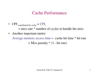
International Research Research and Development (IJTSRD) International Open Access Journal A Performance Degradation Tolerance Way Tagged Cache Karkagari Anjali1, G. Kumara Swamy2, M. Preethi2 1PG Scholar, 2Assistant Professor CMR Institute of Technology, Hyderabad, Telangana, India International Journal of Trend in Scientific Scientific (IJTSRD) International Open Access Journal ISSN No: 2456 ISSN No: 2456 - 6470 | www.ijtsrd.com | Volume 6470 | www.ijtsrd.com | Volume - 2 | Issue – 5 A Performance Degradation Tolerance Way Tagged Cache A Performance Degradation Tolerance Way Tagged Cache Karkagari Anjali 1 CMR Institute of Technology, Hyderabad, that is committed to upgrading the system performance. To help PDT, the issues of: The fraction of PDEF in the target design The induced performance loss by PDEF should be addresses Despite the fact that in it has been demonstrated that the idea of PDEF is relevant to the branch directing indicator, this may not continuously be the sit for other execution improvement modules in a processor design. For instance, the cache design that involves a bigger area in recent processors is normally used to quicken the instructions/data get to process by replicating a subset of the instructio slow speed main memory to the small size and fast memory. 2. MEMORY ORGANIZATION 2.1 Basic types and parameters of memory devices in computers Computer memories constitute a common unique system for execution of the program. Memory in computers are utilized for putting away unique types of data, for example, information, programs, addresses, literary records and status data on the processor and other Computer devices. Data put away in memory devices can be separated into bits words, pages, and other bigger information structures, which have their own identifiers. In primary memory, data is put away in memory cells or memory areas. Memory areas contain data to which an entrance can occur. To read or write data in a memo single memory access task must be executed, which requires independent control signs to be provided to the memory. ABSTRACT For an electronic product or chip if functional faults exist, then the product or chip is of no use. Therefore, if we take a cache memory, a secondary memory for high-speed retrieval of data stored where functional faults exist. These functional faults in the data stored in the cache can be converted into performance faults so that the caches can still be marketable. In processors, caches are designed as Level 1(L1), Level 2(L2), and the least hard disk. If the processor wants the data from/to memory it checks the availability of data in upper-level cache L1 and if the data is found it sends to the processor. If the data is not found in L1, it checks in lower level cache L2 and next in at the least in slow memory or hard disk. So, in this process, many functional faults may exist which leads to making the processor faulty. So, to protect the cache memory ECC and BIST are used. For a cache redesign, a PDT cache is used where functional faults are converted into performance faults. We propose a new PDT way tagged cache design which leads to increased performance. This reduces fault rate with small hardware overhead by applying BIST or ECC method. For an electronic product or chip if functional faults exist, then the product or chip is of no use. Therefore, if we take a cache memory, a secondary memory for speed retrieval of data stored where functional that is committed to upgrading the system performance. To help PDT, the issues of: The fraction of PDEF in the target design The induced performance loss by PDEF should be the data stored in the cache can be converted into performance faults so that the caches can still be marketable. In Level 1(L1), Level Despite the fact that in it has been demonstrated that the idea of PDEF is relevant to the branch directing indicator, this may not continuously be the situation for other execution improvement modules in a processor design. For instance, the cache design that involves a bigger area in recent processors is normally used to quicken the instructions/data get to process by replicating a subset of the instructions/data stored in slow speed main memory to the small size and fast , and the least hard disk. If the processor wants cks the availability of and if the data is found it sends to the processor. If the data is not found in L1, and next in L3 and at the least in slow memory or hard disk. So, in this y functional faults may exist which leads to making the processor faulty. So, to protect the are used. For a cache redesign, a PDT cache is used where functional faults are converted into performance faults. We propose a ay tagged cache design which leads to increased performance. This reduces fault rate with small hardware overhead by applying BIST or ECC MEMORY ORGANIZATION Basic types and parameters of memory Computer memories constitute a common unique system for execution of the program. Memory devices in computers are utilized for putting away unique types of data, for example, information, programs, addresses, literary records and status data on the processor and other Computer devices. Data put away in memory devices can be separated into bits, bytes, words, pages, and other bigger information structures, which have their own identifiers. In primary memory, data is put away in memory cells or memory areas. Memory areas contain data to which an entrance can occur. To read or write data in a memory location, a single memory access task must be executed, which requires independent control signs to be provided to Keywords: Cache memory, PDT, Memory Hierarchy, BIST, fault , Memory Hierarchy, 1. INTRODUCTION Recently, performance degradation tolerance (PDT) has been proposed as another approach to outline and test a reliable system. The focal point of PDT is on the specific performance shortcomings that actuate some execution corruption of a system without bri about any mistakes for the computational outcomes. It has been demonstrated that this thought is appropriate to numerous segments in a superior processor outline Recently, performance degradation tolerance (PDT) has been proposed as another approach to outline and test a reliable system. The focal point of PDT is on the specific performance shortcomings that actuate some execution corruption of a system without bringing about any mistakes for the computational outcomes. It has been demonstrated that this thought is appropriate to numerous segments in a superior processor outline @ IJTSRD | Available Online @ www.ijtsrd.com @ IJTSRD | Available Online @ www.ijtsrd.com | Volume – 2 | Issue – 5 | Jul-Aug 2018 Page: 1
International Journal of Trend in Scientific Research and Development (IJTSRD) ISSN: 2456-6470 In view of data addressing technique, memory devices can be classified into two: In which access to location is controlled by addresses, Access to locations is controlled by the memory content. In the first type memories, accessible locations have a place in which each available a location has its address that can be utilized to choose a location in the memory and execute an operation. These are memories which are addressed, depend on hardware circuits, which do address decoding and select the required location for a memory access operation. The total addresses in a given memory are called an address space of this memory. In the second type, the selection of a memory location is done by comparing with the contents of the memory. The positive result of comparison gives the readout of the remaining data in that location. Whereas, for a write operation, basic data, which will be accessed in the future, an extra information is stored in each location, which will be used for searching the basic data using a comparative method. These memories do not have address decoders. Memories addressed by address are again classified into three: 1.Random access memories 2.Sequential access memories 3.Cyclic access memories. 2.1.1 Random Access Memories: An irregular access memory has no restriction for in space and time access to any location at any address in the address space. The access is done independently on the request of every past accesses. The access can occur to addresses in any order. Each location in a random-access memory has independent hardware circuits that give the access. These circuits are controlled by address decoding. 2.1.2 Sequential Access Memories: A sequential access memory enables locations which have consecutive addresses in the memory address space. In these memories, data is sequentially stored on the data carrier, e.g. magnetic tape. Access to information happens while during writing or reading the storage under control of a control unit, which checks locations of neighboring areas. Ex: optical disk, magnetic tape etc. 2.1.3 Cyclic Access Memories: A cyclic access memory is a memory in which get to is constrained to areas that have back to back addresses in the address space processed modulo certain subspace of that address space. Data is put away on a data carrier that constitutes a circle or a set of loops. This results that in some place on the carrier there is an unexpected difference in the address from the biggest to the littlest one. In such recollections, access to information happens while the carrier moves in regard to the write or reading of device, under control of a control unit, which checks locations of neighboring areas. Ex: Magnetic disk memory. 2.2 Memory Hierarchy in Computers: Memory devices in computers can be classified relying upon their access time and their distance from the processor, which implies the number of primary transfers when information is fetched. These classifications have comparable parameters, for example, access time, cycle duration, volume, information storage cost per bit. The groups can be set according to the direct access among the components in the figure 2.1, where the vertical access represents memory speed and access, horizontal axis represents memory volume and cost. A register memory takes the nearest position in regard to the processor ALU. It is an arrangement of processor registers. It includes a low access time, little volume, high cost/bit and fast. Figure 2.1 Memory Hierarchy @ IJTSRD | Available Online @ www.ijtsrd.com | Volume – 2 | Issue – 5 | Jul-Aug 2018 Page: 2
International Journal of Trend in Scientific Research and Development (IJTSRD) ISSN: 2456-6470 A computer cache memory is situated at a more distance from ALU. It is a rapid random-access memory, in which duplicates of at present utilized information and instructions stored and got from the primary memory. A cache memory can be normal or separate for information and instructions. It includes rapid, low access and process durations, low volume and high cost per bit. It is at present working as a static semiconductor RAM memory. Main memory is situated at the medium position. It holds current information and instructions of executed programs. It has a large capacity, minimal cost/bit, medium speed and medium process duration. It is as of now worked as a dynamic semiconductor RAM memory. Auxiliary memory is found at the largest distance from the ALU. It has a large volume, minimal cost/bit, moderately slow memory with a vast access and cycle duration. The auxiliary memory can be further inside subdivided into a few levels that vary in the access time and volume: cache disk memory, main disk memory, Magnetic tape memory or optical disk memory. The various levels of the memory hierarchy are shown below in figure 2.2. 3. CACHE MEMORY A cache memory is a quick arbitrary access memory where the computer stores data that is currently utilized by programs (data and instruction), stacked from the primary memory. The cache has shorter access time than the main memory due to the costly implementation technology. The cache has a restricted volume because of the properties of the applied technology. The data to the cache memory is utilized more than, the access time to it will be much shorter than for the situation if this data were retrieved in the primary memory and the program will execute at a higher speed. Time efficiency of utilizing cache comes from the locality of access to data that is seen amid program execution. We see here time and space locality: Time locality comprises to utilize similar instructions and data in programs amid neighboring time interims as many times. Space Locality is a tendency to store instructions and data utilized as a part of a program in short separations of time under neighboring locations in the main memory. Because of these localities, the data stacked to the cache memory is utilized a few times and the execution time of programs is highly diminished. The cache can be executed as a multi-level memory. Contemporary PCs, for the most part, have two levels of cache storage. In old PC models, a cache memory was introduced outside a processor. The access to it was composed over the processor outer system bus. In the present PCs, the primary level of the cache memory is introduced in the same IC as the processor. It altogether accelerates processor's co-operation with the cache. Few chips have the second level of cache memory put additionally in the processor's circuit. The volume of the primary level cache is from a few thousand to a few a huge number of bytes. The second level has the volume of several hundred thousand bytes. A cache memory is kept up by an exceptional processor subsystem called cache controller. In the event that there is a store memory in a computer, at that point at each entrance to the main memory, the processor sends an address to cache in order to retrieve data. The cache control unit checks if the asked data exists in the cache or not. Assuming if the cache has the data, this is the case, we have a "hit" Figure 2.2 Data exchange between memory hierarchy @ IJTSRD | Available Online @ www.ijtsrd.com | Volume – 2 | Issue – 5 | Jul-Aug 2018 Page: 3
International Journal of Trend in Scientific Research and Development (IJTSRD) ISSN: 2456-6470 as an extra subsystem associated with the framework transport that interfaces the processor with the principle memory, as a subsystem that intermediates between the processor and the principle memory, as a different subsystem associated with the processor, in parallel in regards to the principal memory. The third arrangement is connected the most as often as possible. 3.2 Information Organization and Mapping in Cache Memory: Three basic mapping methods used for mapping information fetched from the main memory to the cache memory: associative mapping direct mapping Set-associative mapping. 4. PDT CACHE 4.1 Cache Access Mechanism: The total number of PDEF can be maximized by modifying the access mechanism of a cache. Cache checks the availability of requested data when receiving the access request given by the processor. This is done by: Check if the word is valid or not Access a particular word which is indexed by the memory address Check if the tag (a specific part of address memory) is matched with the word that is accessed in the cache and if it's a hit, the processor gets the data. Otherwise, a miss occurs and data is retrieved to the processor from main memory or lower level memory (L2) PDT cache implementation is done as follows. When the processor wants the data, it accesses the target- level I cache with the same memory address. At the same time, this address is sent to the lower level (I+1) cache parallelly. The data transferred from (I+1) cache assumed to be correct, then this data is checked with level I cache for the correctness of the data. The time required for waiting for the data access in the level (I+1) cache is hidden by the time required for pipeline execution of instructions. Here the retrieved data in level I cache is incorrect and data from level (I+1) will be used by the processor instead. The target instruction cycle completes its execution by level(I+1) cache even before the corrected data is required for and the requested data is retrieved from the cache. The activities worried about a reading with a hit appear in the figure 3.1 beneath. Figure 3.1 Read implementation in cache memory on Hit In the other case, if requested data is not there in the cache, then it is a "miss" and the data is brought from the main memory to the cache and to the processor unit. The data isn't replicated in the cache as single words yet as a bigger square of a fixed volume. Together with the data block, a piece of the address of the start of the block is constantly copied into the cache. This piece of the address is next utilized at readout during identification of information block. The activities executed in a cache memory on "miss" are demonstrated as follows in figure 3.2. Figure 3.2 Read Implementation in cache memory on Miss To clear the clarifications, we have accepted a solitary level of cache memory underneath. On the off chance that there are two cache levels, at that point on "miss" at the primary level, the address is moved in a hardwired route to the cache at the second level. In the event that at this level a "hit" happens, the data that contains the asked word is brought from the second level cache to the first level reserve. In the event that a "miss" happens likewise at the second reserve level, the blocks containing the asked for word are brought to the cache memories at the two levels. The size of the cache at the principal level is from 8 to several tens of bytes. Size of the second level is commonly bigger than that at the main level. The cache memory can be associated with various approaches to the processor and the primary memory: @ IJTSRD | Available Online @ www.ijtsrd.com | Volume – 2 | Issue – 5 | Jul-Aug 2018 Page: 4
International Journal of Trend in Scientific Research and Development (IJTSRD) ISSN: 2456-6470 re-execution with takes more time if pipeline fetching is needed with the corrected data with increased hardware overhead. 4.2 Cache Access State Diagram: In the state diagram, figure 4.1, when the processor is requesting the data, Req_P is raised. When the Req_P is given, the FMOut signal is given by faulty map to check whether the cache word to be accessed is correct or not. If the cache word is correct, FmOut is signal is deactivated and cache sends the required data if it's a hit or data is accessed from the lower level cache. Read and Write operations are as follows: the data to lower cache memory. Then after caches go to Write Data state to write data in the current level cache. Then the cache goes to the IDLE state in next clock cycle. Some new state transitions are used but no new states are used for the faulty condition. Readmission or Write Miss states are used when the incorrect word is accessed. Functional correctness is achieved as the level(i+1) is protected, since the data is stored in level I and level (i+1), the correct word can be retrieved/written from/to lower level cache memory. 5. CONCLUSION In this project a new cache design to support PDT is proposed. Faults in the data storage cells in our cache design can be tolerated at the cost of some performance degradation. More importantly, the fault tolerability of our method is flexible, depending on the acceptable threshold of degraded performance. Since the implementation of the proposed design is simple, the users can easily increase the effective yield of caches using our method. The experimental results also demonstrate the general applicability of our method to caches. AUTHORS PROFILE: Karkagari Anjali, She received Bachelors’ of Degree in 2015 from Electronics & Communication of Engineering from Vignan Institute of Technology and science. She is pursuing M.Tech in VLSI System Design from CMR Technology. Mr. G Kumara Swamy (M.Tech), He is working as Assistant Professor in CMR Institute of Technology, He did Masters in VLSI DESIGN from CVR Engineering College. Ms. M. Preethi (M.Tech - ES), she is working as Assistant Professor in CMR Institute of Technology. She has Masters in EMBEDDED SYSTEM. Figure 5.1 The state diagram of PDT cache Read Hit: Read hit happens if the accessed cache word is valid with the matched tag, then the cache returns data and returns to an IDLE state until it is accessed again. Read Miss: In the current level cache, if the requested does not exist or if the cache data is invalid, the cache goes to Read Miss state and lower level cache receives the request. In next cycle, cache goes to Wait Read state and remains in this state until Ready M is raised when the requested data is ready by the lower level cache. After that cache goes to Read Data state to get and to send the data to the processor. Write Hit and Write Miss: Write through policy is used here. In all levels of cache, data has to be written. Write hit and Write miss differs in whether to allocate a new word or not. Cache control unit sends a signal to write the data to lower level cache after hit/miss condition is checked. Cache goes to WaitWrite state after a clock cycle until Ready_M is raised. At this state, the signal indicates when to write Institute of @ IJTSRD | Available Online @ www.ijtsrd.com | Volume – 2 | Issue – 5 | Jul-Aug 2018 Page: 5