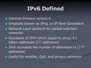
Understanding SONET: High-Speed Fiber Optic Transmission Standards
SONET (Synchronous Optical Networking) is a standardized protocol for high-speed fiber-optic communications, enabling the efficient transmission of data with low error rates. It facilitates interoperability among various telecom entities, utilizing both synchronous and asynchronous transfer modes within a structured framework of Optical Carrier (OC-N) levels. SONET incorporates four architectural layers addressing physical characteristics, multiplexing, and data transport management. Additionally, it supports diverse payload types and ensures robust network management through Communication Channels and Digital Cross-Connects.

Understanding SONET: High-Speed Fiber Optic Transmission Standards
E N D
Presentation Transcript
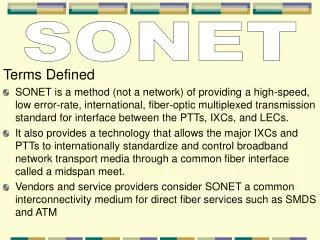
SONET Terms Defined • SONET is a method (not a network) of providing a high-speed, low error-rate, international, fiber-optic multiplexed transmission standard for interface between the PTTs, IXCs, and LECs. • It also provides a technology that allows the major IXCs and PTTs to internationally standardize and control broadband network transport media through a common fiber interface called a midspan meet. • Vendors and service providers consider SONET a common interconnectivity medium for direct fiber services such as SMDS and ATM
SONET • SONET uses both synchronous and asynchronous transfer modes through the use of a fixed data-transfer frame format including user data, management, maintenance, and overhead. STANDARDS • SONET standards have been introduced in three phases: • Phase I : Hardware specifications • Phase II: multiple vendor connectivity and management • Phase III: builds upon Phase II providing additional network management, performance monitoring, and control functions.
SONET SONET STRUCTURE • The SONET Optical Carrier (OC-N) structure consists of OC-N levels multiplexed to form higher-speed transport circuits that range into the gigabits range and provide an alternative to aggregating multiple DS1 and DS3 transmission facilities • The basic structure of SONET is built around Synchronous Transport Signal level 1 (STS-1) transport through an Optical Carrier (OC-N) signal over fiber optics. • An aggregate 51,84 Mbps STS-1 bit stream, when converted from “electrical” to “fiber optic” is called Optical Carrier-1 (OC-1) • It is composed of a transmission of 810-byte frames sent at a rate of 8000 times per second.
SONET SONET STRUCTURE (Continue…) • Current SONET speeds range from 51.84 Mbps (OC-1) to 9.95328 Gbps (OC-192) • Any subrate signals below OC-1 are multiplexed to form a single OC-1 channel. • Refer to Table 15.1 (p. 597) • Refer to Table 15.2 (p. 597)
SONET Multiplexing • SONET provides direct multiplexing of both SONET speeds and current asynchronous and synchronous services into the STS-N payload. • Payload types range from DS1 and DS3 to OC-3c and OC-12c ATM and SDH/PDH payloads. • Refer to Figure 15.1 (p.598) • Other major advantage of SONET is that each individual signal down to the DS1 level can be accessed without the need to demultiplex and remultiplex the entire OC-N level signal. • This is commonly accomplished through a SONET Digital Cross-Connect (DXC)
SONET Multiplexing (Continue…) • It is important to note that SONET multiplexing requires an extremely stable clocking source with a stable reference point. • Thus, the frequency of every clock within the network must be the same or synchronous with one another. • This central clocking source must be at least a Stratum level 3 source, with a Stratum 1 preferred for greatest accuracy.
SONET SONET Architecture Layers • There are four layers to the SONET architecture: • physical: defines the physcial fiber type, path, and characteristics • section: builds the SONET frames from either lower SONET interfaces or electrical interfaces • line: provides synchronization, channel multiplexing, and protection switching. • path: manages the actual data transport across the SONET network, as well as the pointer function • Refer to Figure 15.2 (p. 599) • Refer to Figure 15.3 (p. 600)
SONET OC-N Midspan Fiber Meet • The OC-N midspan fiber meet allows CPE, LEC, and IXC hardware from different vendors to interface with each other via SONET. • It provides a single platform base for access from the central office to the CPE • Refer to Figure 15.5 (p. 601)
SONET Data communications Channels (DCC) • SONET transmissions also contain communications channels which transmit network management information between network elements. • This information includes alarm, control, maintenance, and general monitoring status. • Each SONET terminal and regenerator uses a 192 kbps channel, and each optical line between terminal multiplexers uses a 576 kbps channel for the DDC
SONET Frame Format and OAM Elements • SONET frame payloads are not synchronized by a common clock even though SONET is a synchronous technology. • The standard SONET frame has two major pieces - payload and overhead - functional in Phase I implementations. • Refer to Figure 15.6 Payload • The payload is defined as the actual data to be transported across the SONET path. • Payloads can vary depending on the OC speed of transport.
SONET Payload (continue…) • Payloads can take many forms, such as typical T-carrier channels (e.g., DS3), FDDI, SMDS, ATM, or Virtual Tributaries (VTs) of various sizes. • Payloads are backward compatible with the North American, European, and Pacific Rim standard transport technologies (DS and CEPT) • The payload envelope of the frame can vary in size in 774-byte increments, and the term used for the envelope is Synchronous Payload Envelope (SPE) • SONET uses “pointers” to provide synchronization to avoid having timing and slipping problems
SONET Virtual Tributary • Virtual tributaries are the building blocks of the CPE. • The label VTxx designates virtual tributaries of xx Mbps. • These virtual tributaries are labeled as VT1.5 for DS1, VT3 for DS1C (3 Mbps), VT2 for CEPT E1, and VT6 for DS2 (6 Mbps). • Refer to Table 15.3 (p. 607) • VTs are combined to form VT groups. These VT groups consist exclusively of three VT1.5s, four VT2s, two VT3s, or one VT6 within a 9-row by 12-column portion of the SPE
SONET Virtual Tributary (continue…) • VTs can either operate in • “locked mode” - fixes the VT structure within an STS-1 and is designated for channelized operation • “floating mode” - allows these values to be changed by cross-connects and switches and is designated for unchannelized operation. • The common tributary is VT1.5, which supports a virtual tributary of 1.5 Mbps through a DS1 transport envelope. • VTs run from the VT1.5 through a VT6 (DS2) • Refer to Table 15.4 (p. 608)
SONET Synchronization and Pointers • pointers are used by SONET devices to easily identify subchannels down to the DS0 level within a SONET transmission. • These pointers are located within the line overhead portion of each frame. • Refer to Figure 15.12 (p. 609) • pointers are lso used to identify virtual tributaires (VTs) within an SPE
SONET Overhead and the Control Field • The SONET overhead structure parallels the existing telephone network, with three layers to match section, line, and path segments. • Refer to Figure 15.13 (p. 609) Bit Interleave Parity Check (BIP-8) • Parity is provided through a 1-byte Bit Interleave Parity (BIP-8) code at each section, line and path segment of the frame. • The section BIP assures error-free transport between regenerators, • The line BIP assures error-free transport between terminating devices • The path BIP assures error-free transport between line termination equipment.
SONET Bit Stuffing • When the incoming tributary data rates cannot fully meet the STS-N rate, the SONET device performs bit stuffing to achieve the desired badnwidth. • This is as simple as inserting extra bits into the data stream, which are then stripped off at the destination SONET device. • Bit stuffing is also used for frame synchronization. This technique is used when the access hardware and network hardware are using different timing sources having clock frequency differences.
SONET OAM Structure • The Operations, Administration, and Maintenance (OAM) functions of SONET are divided into three levels • F1: defines OAM flows between regenerator sections and between regenerators and LTE • F2: defines OAM flows between LTEs at the termination of section end points. • F3: defines OAM flows between PTE elements that perform payload assembly and disassembly, error check operations, and cell delineation over the transmission path.
SONET SONET Hardware • The most common equipment term used is the SONET terminal. • The word terminal, or terminal adapter, is used at times to represent a SONET multiplexer, DXC, and even a switch. • OC-N -to-OC-N SONET devices, those that provide the interface of OC-12 and OC-48 speeds to higher-speed tributaries like OC-192, are most often called terminals as well. • The primary benefit of SONET Central Office (CO) terminal equipment - terminals, multiplexers, terminal multiplexers, DXCs, and switches - is the reduction of equipment required for DS1, DS3, and OC-N connectivity and interswitch trunking.
SONET SONET Terminating Multiplexers • Terminating multiplexers provide user access to the SONET network • Terminating multiplexers, also called PTE, turn electrical interfaces into optical signals by multiplexing multiple DS1, DS1C, DS2, DS3, or E1 VTs into the STS-N signals required for OC-N transport. • These devices are configured in point-to-point configurations. The most common is the point-to-point, four-fiber configuration over the “line”, where two fibers are connected between two terminals • Refer to Figure 15.16 (p. 614)
SONET SONET Terminating Multiplexers • SONET terminals are typically connected in fiber rings, with each device connected to another through a two-pair fiber configuration. • Refer to Figure 15.17 (p. 614) • For SONET transmission LTE terminal adapters are also used which interface up to 84 DS1s into a single OC-3 interface • Refer to Figure 15.18 (p. 615)
SONET SONET Concentrators • SONET concentrators operate the same way as electrical concentrators and hubs, concentrating OC-3, OC-12, and OC-48 interfaces into higher-transmission rates like OC-192. SONET Add/Drop Multiplexer (SADM) • SONET add/drop multiplexers allow the provider to drop and add not only the lower SONET rates, but also electrical interface rates down to the DS1 level. • Drop-and-insert, drop-and-continue, and broadcast mode are standard features. • Refer to Figure 15.19 (p. 616)
SONET SONET Digital Loop Carrier Systems (DLCs) • Digital Loop Carrier systems (DLCs) are used to concentrate multiple DS0 traffic from remote terminals into a single OC-3 signal. • These devices are typically situated at the LEC and handle both voice and data traffic, providing an interface for non-SONET CPE, LEC, and CO switches to the SONET public network.\ • DLCs have many capabilities and can handle access for many of the data services such as N-ISDN and B-ISDN
SONET SONET Digital Cross-Connects (SDXCs) • SDXCs allow switching andcircuit grooming across all levels fo the transmission down to the DS1 level, including those that interface to the SDXC without being on the incoming or outgoing transmission. • SDXCs provide SONET OC-N level cross-connect provisioning capabilities and can also act as a SONET hub to provide both asynchronous and synchronous user or network access.
SONET SONET Digital Cross-Connects (SDXCs) (Continue..) • SONET DXCs use pointers rather than traditional DXC slip buffers to mark the beginning of a DS1 frame and allow insertion/extraction with minimal delay. • The additional SDXC features include: • Network monitoring and testing • Network provisioning • Maintenance • Network restoration • Refer to Figure 15.20 (p. 618)
SONET SONET Digital Cross-Connects (SDXCs) (Continue..) • SDXCs come into two types: • Wideband (WDXC): lower-speed device which provides cross-connect capability for floating VTs within an STS-N • Broadband (BDXC): higher-speed device which can both cross-connect at DS3 (asynchronous or synchronous) and STS-1 signals and provide concatenation of multiple STS-1 signals to STS-N levels
SONET SONET Broadband Switches • SONET broadband switches provide the switching capability found in major voice switches, but operate at the higher OC-N levels. • Many SONET terminal and switch vendors are now including SDXC capabilities within their switches. • A need also exists for this functionality in the CPE environment interfacing many LAN and MAN technologies. • Refer to Figure 15.23 (p. 620)
SONET SONET Regenerators and Optical Amplifiers • Regenerators reshape and boost signals that have incurred dispersion or attenuation over long transmission distances. SONET Equipment Vendors • SONET hardware terminal vendors can be separated into three categories: • category 1: vendors pushing the SONET DXC • category 2: vendors offer drop-and-insert multiplexer products. • Category 3: vendors advocate integrated SONET message switches. • Most systems today are being installed at OC-48 speeds, with some deployment of OC-192 systems, and are all new hardware devices.
SONET Interfaces • The Network-Node Interface (NNI) specifies the link between existing in-place digital transmission facilities and the SONET network node, as well as the process for converting the electrical signal into optical pulses for network transmission. • This is the primary interface from the electronic world into the optical world. • There are three major SONET interface options: • Direct CPE or CO hardware interface • Gateway device to convert to OC levels • Conversion within the SONET switch itself
SONET Services Support • Typical services to ride over SONET networks include: • Digital Data Service (DDS) • N-ISDN • ATM • X.25/X.75 • Frame Relay • FDDI/FDDI-II • 802.6/SMDS • With SONET, users will be able to dial up whatever bandwidth increments are needed.
Cisco Configuring the Catalyst 1900 Switch
Objectives • Configure the Catalyst 1900 Switch CLI • Configure the Catalyst 1900 Switch Hostname and Passwords • Configure the Catalyst 1900 Switch Security • Configure Virtual LANs • Configure ISL Routing
Features of the 1900 Switch • Types of Operating Systems • IOS-based • Set-based • The Three Configuration Options • Command Line Interface (CLI) • Visual Switch Manager (VSM) • Original Menu System • Menu-based options
Cisco 1900 IOS Configuration Commands • Set the passwords • Set the hostname • Configure the IP address and subnet mask • Identify the interfaces • Set a description on the interfaces • Define the duplex of a port • Verify the configuration
IOS Commands (cont.) • Setting the Passwords • Setting the User Mode and Enable Mode Passwords • Setting the Enable Secret Password
IOS Commands (cont.) • Setting the Hostname • Setting IP Information • Configuring Switch Interfaces • 10BaseT Interfaces • FastEthernet Interfaces • Setting Descriptions • Viewing Descriptions
IOS Commands (cont.) • Configuring the Port Duplex • Options • Verifying IP Connectivity • Erasing the Switch Configuration • Managing the MAC Address Table • Setting Permanent MAC Address Entries • Setting Static MAC Address Entries
IOS Commands (cont.) • Configuring Port Security • Using the Show Version command • Changing the LAN Switch Type
Configuring VLANs • Example >en #config t Enter configuration commands, one per line. End with CNTL/Z (config)#hostname 1900EN 1900EN(config)#vlan 2 name sales 1900En(config)#vlan 3 name marketing 1900En(config)#vlan 4 name mis 1900EN(config)#exit
Configuring VLANs • Assigning Switch Ports to VLANs • Configuring Trunk Ports • Clearing VLANs from Trunk Ports • Verifying Trunk Ports • Configuring ISL Routing
Configuring VTP • Configuring the Domain • Adding to a VTP Domain • VTP Pruning
Restoring or Upgrading the Catalyst 1900 IOS • Command: copy tftp://tftp_host_address/IOS_filename opcode • Backing Up and Restoring the Catalyst 1900 Configuration
CDP with the 1900 Switch • Commands: sh cdp cdp timer cdp holdtime
Summary • Configured the Catalyst 1900 Switch CLI • Configured the Catalyst 1900 Switch Hostname and Passwords • Configured the Catalyst 1900 Switch Security • Configured Virtual LANs • Configured ISL Routing