VCL-TDMoIP (4E1 Port FE Version) Product Presentation
220 likes | 367 Views
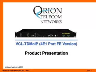
VCL-TDMoIP (4E1 Port FE Version) Product Presentation. Updated: January, 2013. Product Overview. 'VCL-TDMoIP' (4 E1 Port FE Version) equipment supports transmission of up to 4 x E1 links over IP / Ethernet, MEF or MPLS networks

VCL-TDMoIP (4E1 Port FE Version) Product Presentation
E N D
Presentation Transcript
VCL-TDMoIP (4E1 Port FE Version) Product Presentation Updated: January, 2013
Product Overview • 'VCL-TDMoIP' (4 E1 Port FE Version) equipment supports transmission of up to 4 x E1 links over IP / Ethernet, MEF or MPLS networks • Powerful ARM-Cortex Processor which provides a highly reliable clock recovery mechanism for low jitter and wander control, even under variable network conditions • Available with various Electrical (10/100BaseT) and Optical (100BaseFX) Ethernet port options which allow the users to implement 1+1 add-drop (Drop-Insert), Ethernet link redundancy (using Port Trunking / Port Bonding) and 802.1p based QoS mechanisms for network optimization • Optimizes on the network usage, such that the bandwidth used by the TDMoIP equipment on the packet network is limited to the corresponding to the number of E1 Ports and the time-slots that are being transported over the Ethernet / packet network.
Purpose of TDMoIP technology • Telecom companies and enterprise users can save significant network and equipment cost and generate additional revenue by offering different types of services over a single packet-switched infrastructure by the use of TDMoIP equipment • TDMoIP equipment is also suitable for connecting to Ethernet / packet wireless equipment to achieve fast deployment of E1 services over wireless Ethernet networks • One particular application is to build E1 links with low cost Wireless LAN bridges, replacing expensive TDM / E1 microwave radios • Used to provide legacy TDM services over Ethernet optical fiber, or wireless Ethernet/IP networks.
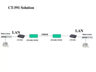
How it works • E1 data streams received on the E1 interfaces are converted by the TDMoIP engine of the TDMoIP equipment to Ethernet data packets (of a fixed size) and transported over the Ethernet network with UDP / IP, MEF or MPLS headers • At the receiving end the TDMoIP reconstructs the original data streams by removing the IP, MEF or MPLS headers and converts the Ethernet data packets back to E1 frames using highly reliable and accurate clock recovery mechanism • Offers the user a choice of standard, E1 to packet and packet to E1 conversion mechanisms that include SAToP and CESoPSN technologies.
Hardware Highlights • 19-Inch rack mountable • 1U form factor (44mm high) • 1+1 Redundant Power Supplies, AC and DC, or AC plus DC • Redundant power supply inputs • Extended Temperature Range: (-200C to +600C) • EMI / EMC Complaint • Real time battery backed clock with life in excess of 10 years • Power over Ethernet (PoE) - Optional
E1 Clock recovery and synchronization techniques: • Adaptive Clock Recovery (ACLK) • Recovered Clock (RCLK) / Loop-Timed Clock • Asymmetrical (One-Clock and Two-Clock) Clock • Synchronization to an External Clock (ECLK) • Synchronization to an Internal Clock • Automatic clock priority selection with fall back • Plesiochronous Clocking.
Key Features - E1 and TDMoIP Interface • Supports 4 independent E1 interfaces • Internal, External, Adaptive, Recovered clock and Asymmetrical (One-Clock and Two-Clock) options for the E1 TDM port synchronization. Automatic clock priority selection with fall back • Absolute and Differential times tamps • Jitter and Wander conforms to G.823 / G.824 and G.8261 and TDM specifications • Supports three E1 framing modes - Framed, Unframed and Multi-framed with CAS signaling • Supports IETF-PWE3 (pseudo-wire), SAToP and CESoPSN transport mechanisms
Key Features - E1 and TDMoIP Interface • Supports CESoPSN payload mechanism to support the fractional E1 with data rate of 64Kbps to 2.048Mbps (DS0 timeslot level). User configurable data rate from 64kbps to 2048kbps, in steps of 64kbps • CESoPSN payload mechanism feature allows the user to optimize the packet switched network by limiting its usage to the corresponding number of timeslots carried by an E1 channel • Supports SAToP payload mechanism to transport full E1 (transparent to the structure of the TDM frame useful for transporting framed / unframed E1 channels) • Supports network latency / packet delay variation / jitter buffer of up to 512ms • Supports IP, MPLS and MEF8 (Metro Ethernet) addressing • 120 ohms balanced E1 interfaces. Optional 75 Ohms BNC interface (120 Ohms to 75 Ohms cables provided) • E1 Loopback facility for testing and diagnostics
Key Features - Ethernet / IP Network Interface • Optical SFP based (1Base-FX) and Electrical (100Base-T) Ethernet port and PoE options • 4 x 10/100BaseT Copper Ports • 2 x 10/100BaseT Copper Ports, 2 x 10/100BaseT Ports with PoE • 2 x 100BaseFX Optical Fiber Ports, 2 x 10/100BaseT Copper Ports • 2 x 100BaseFX Optical Fiber Ports, 2 x 10/100BaseT Ports with PoE • Power over Ethernet (PoE) (available options as above). Meets and exceeds the Telcordia GR-1089-CORE Lighting and Power Contact Protection requirements • VTC Virtual Cable tester on all PHY (Electrical Ethernet) Ports • Point-to-point and point-to-multipoint applications based on IP addressing • Supports drop and insert applications
Key Features - Ethernet / IP Network Interface • 1+1 Ethernet Link Redundancy (Hitless) Redundant Link Protection • Supports QoS, 802.1p based packet priority • Port Control Egress Mode (Tagged/ Un-Tagged/ Un-Modified) 802.1Q Mode • Q-in-Q Tagging • User configurable MTU (TDMoIP payload) packet size. May be configured from 1 to 1800 Bytes • Switch supports jumbo frame sizes of up to 2048 Bytes • Port based and Tag based VLANs Supports 1-4095 VLAN IDs • Supports Ethernet rate limiting on each port • Supports Packet priority assignment (IP Diffserv / DSCP)
System Management, Monitoring and Alarm Interfaces • External Alarm - Dry contact relay alarms are also available at rear of the system to connect the system to an external alarm • NMS (Network Management System) to monitor multiple units from single Central Location • Port Trunking • Supports system temperature monitoring with High Temperature and Low Temperature alarms and SNMP Traps • Supports SNMP V2 Monitoring and Traps • UDP-specific “Special” Ethernet type • In band VCCV ARP
System Management, Monitoring and Alarm Interfaces • Broadcast DA • Self-test for checking system errors upon system bootup • Event Logging • Clock Performance Alarms • Network Performance Alarms • Network Performance Monitoring and Diagnostics • Online / remote upgrade of firmware
System Access, Control and Management Options • Telnet • CLI Control Interface (HyperTerminal or VT100) • SNMP V2 Traps (MIB File provided) • Windows based GUI (Graphical User Interface) for easy configuration, management and access. Ability to monitor multiple units from a single NMS • Password Protection. OAM: Operation and Management Ports • RS232 (DB9) Serial Port • 10/100BaseT Ethernet Management for In-band remote access.
Application Diagram TDMoIP in Cellular Backhaul
Application Diagram Typical Application Diagram in Wireless Network BTS : Base Trans-receiver Station MSC : Master Switching Center RNC : Radio Network Controller LTE : Long Term Evolution FE1 : Fractional E1 FE : Fast Ethernet PoE : Power over Ethernet
Application Diagram Typical Application in Wireless Network - 1+1 Link Redundancy
Application Diagram Typical Application in Wired Network Note: Application illustrate link protection using spanning Tree Protocol between all nodes.
Application Diagram E1s and Gigabit Ethernet Traffic over a Packet Switched Network BTS : Base Trans-receiver Station MSC : Master Switching Center RNC : Radio Network Controller LTE : Long Term Evolution FE1 : Fractional E1 FE : Fast Ethernet GE : Gigabit Ethernet
Power Supply Options • Dual Redundant • 1+1 AC power (100 to 240V AC, 50/60 Hz) • 1+1 DC (-48V) power (40 to 72V DC) • 1+1 DC (-24V) power (18 to 40V DC) • AC plus DC (AC + DC), AC or DC • EMI/EMC compliant. Command Language • Windows based GUI (Graphical User Interface) • Command Line Interface (English text commands).
Management and Control Interfaces • COM Port (RS232 Serial Port) • 10/100BaseT Ethernet Port (each multiplexer may be assigned an IP address and connected to a LAN / IP network for remote access and management through the 10/100BaseT Ethernet Port for in-band configuration, management and access) • Telnet • SNMP, V2 • Additionally, a Windows based GUI (Graphical User Interface) for easy configuration, management and access.
Regulatory Compliance • Safety - IEC 60950 Safety - IEC 60950 • CE • RoHS • Complies to ANS/IEC standards • Complies with Telecom Part 68, FCC Part 15 and CISPR 22 Class A • EMC EN55022: 1998 + A1 and A2 • EMC EN55024 • Operation ETS 300 019 Class 3.2 • Storage ETS 300 019 Class 1.2 • Transportation ETS 300 019 Class 2.3
Thank you for your attention For more details visit us at our Website at http://www.oriontelecom.com Headquarters: Phoenix, Arizona Orion Telecom Networks Inc. 16810, Avenue of the Fountains, Suite # 108, Fountain Hills, AZ 85268 U.S.A. Phone: +1 480-816-8672, Fax: +1 480-816-0115 E-mail: sales@oriontelecom.com Website: http://www.oriontelecom.com Regional Office: Miami, Florida Orion Telecom Networks Inc. 4000 Ponce de Leon Blvd. Suite 470, Coral Gables, FL 33146 U.S.A. Phone: 1-305-777-0419, Fax: 1-305-777-0201 E-mail: sales@oriontelecom.com Website: http://www.oriontelecom.com