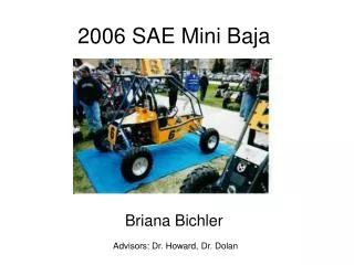
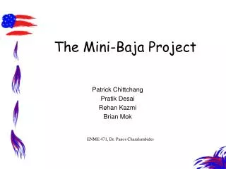
The Mini-Baja Project
The Mini-Baja Project. Patrick Chittchang Pratik Desai Rehan Kazmi Brian Mok. ENME 471, Dr. Panos Charalambides. Outline. Project Objectives Design Methodology Boundary Conditions Mini-Baja Frames Results Conclusions Questions. Project Objectives.

The Mini-Baja Project
E N D
Presentation Transcript
The Mini-Baja Project Patrick Chittchang Pratik Desai Rehan Kazmi Brian Mok ENME 471, Dr. Panos Charalambides
Outline • Project Objectives • Design Methodology • Boundary Conditions • Mini-Baja Frames • Results • Conclusions • Questions
Project Objectives • To develop a frame that conforms to the SAE standards • To develop a frame that is streamlined, low-weight and safe for the driver and other competitors. • Optimize the Stress-Weight tradeoff. • Cost effectiveness.
SAE Specifications for the Mini-Baja • The roll cage must satisfy SAE requirements for space and strength (minimum size 1-inch ODx0.083 thickness DOM steel tubing). • Side bars with a height of 8-inches (min.) above the lowest point of the “seat of the pants” of the driver. • Maximum time for a driver to exit the vehicle is five seconds. • Transportable via standard pickup trucks with eight foot beds. • Consider the aesthetics of the frame as well as the strength and size requirements.
Design Tasks • Perform simulation on all Mini-Baja models. • Analyze and Evaluate the stress distributions. • Drivers’ safety First • Optimize Stress Vs Weight relationship. • Modify and finalize the model
Model Development Pre-Processing • Element: Linear Isotropic 1 D Beam Element with Circular Cross-Section • Material: 1020 DOM Steel (Driven Over Mandrel) • Apply Boundary Conditions • Symmetry/ • Anti-Symmetry Processing • Meshing • Solve the model using I-DEAS® Post Processing • Data Analysis • Make informed choices to meet the design objective
Loading Cases • Six loading conditions: • Rollover • Front Bump • Rear Bump • Frontal Collision • Heave • Twist Ditch
Frontal Collision Test Test: Frontal Collision Model used: Half model Condition: Symmetry Loading: a uniformly distributed 1680 lb force in X-direction at the front of the vehicle Boundary Condition: Rear corner:Trans X=Y=Z=0 Opp.Rear corner:Trans X=Y=0 Front corner:Trans Y=0 Opp.Front corner: Trans Y=Z=0
Heave Loading Test: Heave Loading Model used: Half model Loading: Engine and Driver load = (100 +210)*3= 630 lbs Boundary Conditions: One rear corner: X,Y & Z =0 Opposite rear corner: X &Y = 0 One Front Corner: Y = 0
Rollover Test Test: Rollover Model Used: Full Loading: Rollover loading considered is 9.42G acting on one of the top front joints of the frame Vertical load: 4200lbs Fore & Aft load: 3080lbs Lateral load: 840lbs
F One Front Wheel Bump Test Test: Front Bump Model used: Full model Loading: a point force of 1680 lbs in the Y-direction of the front corner node Boundary Conditions: Rear corner:Trans X=Y=Z=0 Opp.Rear corner:Trans X=Y=0 Opp.Front corner: Trans Y=Z=0 Other corner: Simulate the force equal to 3 X Total Vehicle Weight = 1680 lbs
F One Rear Wheel Bump Test Test: Rear Bump Model used: Full model Loading: 1680 lbs in Y-direction of the rear corner node Boundary Conditions: • Front corner:Trans X=Y=Z=0 • Opposite Front corner: Trans X=Y=0 • Rear corner: Trans Y=Z=0 • Other corner: Simulate the force equal to 3 X Total Vehicle Weight = 1680 lbs
Twist Ditch Test Test: Twist Ditch Model used: Half model (Anti-Symmetric) Loading: Engine and Driver load = (100 +210)*3= 630 lbs Boundary Conditions: • One rear corner: X,Y & Z =0 • Opposite rear corner: X &Y = 0 • One Front Corner: Y = 0
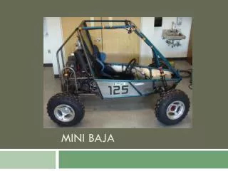
Designed Frames Model 1- Bubble This is the base model given to us by the problem definition Model 2-Buttercup An over-designed version in order to first pass the model successfully through the six severe loading conditions Model 3-Blossom Getting the right mix between stress reduction and weight optimization paradigm
Model 1 - Bubble • Model 1 (the original frame) • Elements are all 1 x 0.083 inch tubing • Six loading tests
Nodes and Elements-Bubble Elements are 1 x 0.083 tubing throughout the frame
Bubble Results • Passed: • Frontal Collision • Heave • Twist Ditch • Failed: • Rollover :34 elements • Front Bump : 16 elements • Rear Bump : 25 elements
Rollover Test Real Time Model Displacement Von-Mises Stress Green: Pass Red: Failed
Roll over and Bump tests were the most severe Von Mises Stress is used as a critical design parameter The model needs to be “beefed” up in the drivers compartment Decide viable way to increase the stiffness of the overall structure Essentially the major goal for the next step was to pass the model Minimization of overall weight Model 1 test results and observations
Modeling Tasks for Model 2 • Reconfigure the roll cage. • Making sure the frame passes rollover and bump tests. • Add cross members to the top of the drivers compartment and back windshield in order to triangulate the stresses • Separate the drivers compartment from the engine compartment by adding a beam. • Add members to the side of the drivers carriage (below). • Resist the temptation to add a cross member that would block the drivers access in and out of the Mini-Baja.
Model 2- Buttercup Tube Sizes Induces Drastic Weight Changes
Test results and Observation • Buttercup passed all the tests • Weight: 128 lbs • 5 types of different Tubes
Modeling Tasks for Model 3 • Design Reform • Experiment with curve beam • Difficulties • Solutions • Point Load • Distributed Load
Model 3 Curvature Curve makes everything Beautiful
Blossom Test Results • Strength: Weight and Aesthetic • The weight : 120lbs • 4 different Types of Tube • Passed all the six loading cases • Aerodynamic shape
Conclusions • Bubble was the lightest but it failed miserably under most of the loading conditions • The second model-Buttercup was developed by modifying the first model making changes in the tube X-section and adding more elements. It passed all the loading conditions but was really heavy to be used as our final design • Blossom: Great Looks with Excellent Performance
Credits We extend our sincere thanks to all the people who made this project possible Our special thanks to Dr. Panos Charalambides for providing the opportunity to gain an insight into the finite elements intricacies We also would like to thank UMBC for providing us with the facilities required to complete the project AND FINALLY: • We wish all the best to our classmates who are graduating this semester . • -GOOD LUCK GUYS