Download
1 / 31
310 likes | 478 Views
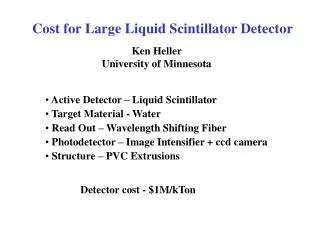
Electronics for the Liquid Scintillator OA Detector Option. Summary of Cambridge Workshop. Alfons Weber Feb 2004. with help from: ANL, Cambridge, FNAL, Harvard, RAL, UMN. System Overview. Physics Specifications light level, noise APDs FE chip Measurements (Leon) Readout Architecture

E N D
Electronics for the Liquid Scintillator OA Detector Option Summary of Cambridge Workshop Alfons Weber Feb 2004 with help from: ANL, Cambridge, FNAL, Harvard, RAL, UMN
System Overview • Physics Specifications • light level, noise • APDs • FE chip • Measurements (Leon) • Readout Architecture • Analogue or digital pipeline • DAQ system • Timing System • R&D for the next year
Requirements (I) • Signal size • Sensitive to MIP from 14.4 m into detector • 25 pe • How many electrons is this? • signal 2500 electrons, noise 500e (250e) • Dynamic range (8bits) • 25 pe = 1 mip = 5 ADC • 4 (near/far) x 5 ADC x 5(no of mips) = 100 ADC • Livetime • For beam physics • no deadtime around spill • For SN (Not proven) advantage*feasibility/cost=low • no deadtime for 10 sec ? • For calibration (cosmics) • maximize livetime out of spill (100 spills / 1sec) • Charge pulse
Requirements (II) • Possible Triggers • External Trigger • Spill • SN • random • Internal Trigger (not necessary) • neutrino interactions • cosmics • (SN) • Near Detector compatibility ? • many overlapping events during 10 usec • Different electronics (fast) • Failure rate • <<10-5 day = 1 every 10 days • MTBF = 105 x 24 h
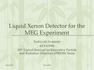
- Ar coating Electric Field Collection Region h+ Si Avalanche region e p Contact layer Contact layer n- Drift n Substrate ++ n + APD Operation Roger is with Hamamatsu now A dime (10¢) Two 16-channel arrays Electrons generated by the incident light are multiplied in the high field region at the junction.
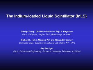
- + Noise Noise Sources Fluctuations on signal Fluctuations on thermal electrons Excess noise factor – Gaussian Variance = F - 1 Johnson noise at the pre-amp input – Gaussian. Preamp ADC
Off Axis APD Readout (analogue) Proof of principle: existing MASDA chip (FNAL) in spill analogue pipeline, out of spill digitisationNOT optimised to imput capacitance
Off Axis APD Readout (digital) • Features • Slowly leaking integrator : falltime constant - Tf • Controlled risetime : Tr • Multiple samples separated by Ts/2 ADC digitizes data every Ts/2 • Tr<<Ts<<Tf • Sample subtractions done on digital data within FPGA • investigated by Harvard Front end chip Tf Ts FPGA Tr Ethernet ADC @ Ts/2 continues digitisation: digital pipeline, regular reset
Multiple Correlated Samples • Do not only sample pulse before and after APD signal • Use multiple samples to reduce noise • Digitisation and low noise amplifier SimulationsbyJohn Oliver Ts 3Ts
Multiple Correlated Samples Conclusion Using 8 samples, improvement is of order ~ sqt(2) Other optimizations possible : e.g. Use samples below & above optimal Noise improvement of > 30% or more are possible ….. and best of all, its free !
APD Box • Receive optical signals • house FE electronics • house digitisation • interface to DAQ
PCB Sideview • Put bare APD onto PCB • Flip-chip alignment to <<150 μm (Ray Yarema) • cool APD to 00F
APD Box (II) • Difficult! • Needs dedicated electro-mechanical engineering (FNAL, UMN) • To be considered: • optical & digital & LV connections • light tight • condensation • noise insulation (external & digital) • heat load from cooled APDs • …
Heat sink Peltier element Alignment collar USB connection APD array Light seal APD Box (design idea)
DAQ System (RAL) • Readout/DAQ is cost sensitive item • Want: • Low cost per channel • Scalable, flexible system • Minimise off-detector links (major cost item) • Use standard technology where possible • Future upgrade paths considered • Aggregate data from multiple APD boxes (96) • Use (Gbit) Ethernet for off-detector links • Total throughput scales with increased links • COTS technology for DAQ backend
Input constraints • 10,000 APD boxes • 64 channels / box (2 scintillator modules) • 8 Byte/channel @ 2 MHz • Continuous sampling, but ZERO suppressed • Assume spill = 20 µs • Data rate • Noise: 10-3 x 2 MHz x 8 Byte, Signal: 0 Hz • 1 MB/s per APD box = 10 GB/s total raw data rate • 20 bytes per spill per APD box • 200 kBytes per spill • 100 Hz readout rate = 20 MB/s total rate
Readout Development @ RAL FPGA development boards Ethernet link optional ADC daughter board LVDS links
Clock & Timing System • FE needs timing to be synchronisedacross the detector • FE may need accurate spill signal • in time: analogue pipeline • not to late: digital pipeline • Need to get spill signal from FNAL to OA site • Need to distribute clock around the detector.
Start Cycle Extract Flat Top MI Timing Events (I)
MI Timing Events (II) • Signals available • Start of NuMI cycle (earliest) • ~1.4 sec in advance: $23 & $A5 • predicts spill to within 1/60 Hz = 16.6 msec • spill-to-spill jitter: 20 µsec • Flat top • ~0.4 sec in advance: $25 • spill-to-spill jitter: 10 µsec??? • Kicker fire (most accurate) • few µsec in advance: $74 & $A9 • spill-to-spill jitter: nsec ???
Signal Transmission • Conventional HEP timing signal distribution at OA site • But:How do we get the spill signal to the detector? • Options: • Internet (slow, ~0.5 sec latency ?) • Phone line (fast, msec latency) • Dedicated radio transmitter (fast)
R&D Plans for FY04. • Objectives: • Demonstrate readout of 14.5 m long strip with cooled APD. • Build ~ 5 readout boxes with un-optimized Mazda chip and packaged APD’s – analog store • Build 1 prototype readout box with digital store. • Design and cost APD readout box • Design for manufacturability. • Thermal, optical and electrical. • Refine system cost estimate. • DAQ specification.
R&D in 2004 - Deliverables • Readout Modules for readout of 14.4 m tubes. • analogue pipeline (MASDA) • digital pipeline • Engineering and Design. • Gbit Ethernet on FPGA • Clock & Timing system • APD box • Power distribution system • Detailed system cost estimate.
APD Box Functions (SAB) • Slave and Master APD Box • Receive clock/spill signal • Digitise/timestamp APD signals • Sparcify data (zero suppression) • Transmit data for “spill” on request • All implemented in FPGA (firmware) • Master APD Box only • Receive clock/ctrl signals from timing system • Re-transmit clock/ctrl on SAB ring • Read out SAB via ring • SABs are daisy-chained • Ring architecture: each SAB can be accessed on either leg • Redundancy: save against single SAB failure • Encapsulate data and transmit it to Readout Concentration Node • 95 SAB are read out by one MAB (8 planes)
Digital Functionality in APD Box • Ethernet & clock only needed for MAB • RAM optional • top part isolated from light-tight box Ethernet SAB ring SAB ring clock power PHY PSU monitoring & control RAM FPGA T ADC ADC analogue amplifier & APD
Readout Concentrator Node (RCN) • RCN is a standard PC • with several network cards • In Spill mode: • Receive data from several 4-16 MABs over Ethernet, i.e. 8 RCNs needed • Traffic shaping and buffering • Transmit data to Trigger Processing Nodes • Also in self-triggering mode (only): • Receive trigger primitives/Make L1 trigger decision • Broadcast trigger time to MABs & other RCN • Receive data for trigger time • More RCNs possible
Trigger Farm / Data Merging • One Master RCN • coordinating transfer of data to trigger farm • Trigger Processing Nodes (TPNs) • All detector data together for the first time • Run S/W trigger algorithm(s) to identify events • Cosmics • Beam events • ??? • Data Merging node takes data from TPNs for storage • Can easily take many spill triggers / sec