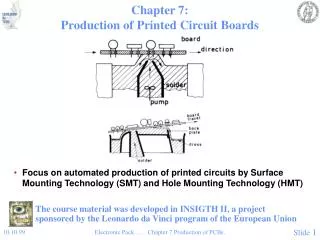
WAVEGUIDES IN BOARDS BASED ON ORMOCER s
WAVEGUIDES IN BOARDS BASED ON ORMOCER s. geert.van.steenberge@intec.ugent.be. Outline. Introduction ORMOCER s Laser ablation Waveguides Deflecting optics Coupling structure Conclusion. Introduction. Integration of optical interconnects on board level Approaches Fiber based

WAVEGUIDES IN BOARDS BASED ON ORMOCER s
E N D
Presentation Transcript
WAVEGUIDES IN BOARDS BASED ON ORMOCERs geert.van.steenberge@intec.ugent.be IMEC - INTEC Department of Information Technology http://www.intec.ugent.be
Outline • Introduction • ORMOCERs • Laser ablation • Waveguides • Deflecting optics • Coupling structure • Conclusion INTEC - Department of Information Technology
Introduction • Integration of optical interconnects on board level • Approaches • Fiber based • Waveguide based • glass sheet • polymers http://www.circuitree.comPrinted Optical Waveguides: The Next Interconnect (H.Holden) INTEC - Department of Information Technology
ORMOCERs • ORganic Modified CERamics • Fraunhofer Institute - Germany • Inorganic-Organic Hybrid Polymers • Applications • microoptical elements (lenses, lens arrays, gratings, prisms) • vertical integration: stacked optical waveguides (wafer scale) • board level optical interconnects • General properties • Compatibility with PCB manufacturing • lamination 180°C 200 Pascals • assembly (solder reflow) up to 250°C • Good planarisation properties • RMS roughness 2 - 4 nm • Long-term stability under variable environmental conditions (humidity, temperature) • Low shrinkage INTEC - Department of Information Technology
ORMOCERs • Optical properties (www.microresist.de) • Refractive index @ 830 nm (adjustable) • CORE 1.5475 • CLADDING 1.5306 • Attenuation • Waveguides • Photolithography • Laser ablation INTEC - Department of Information Technology
ORMOCERs • Application scheme flood exposure applicationspin-coating softbake80-120 °C, <5 min post exposure bake80-120 °C, <5 min exposure laser ablation curing120-240 °C, up to 3 hrs curing120-240 °C, up to 3 hrs development INTEC - Department of Information Technology
Laser ablation • Set-up KrF Excimer Laser(can be tilted)248 nm CO2 Laser9.6 m Frequency tripledNd-YAG Laser355 nm INTEC - Department of Information Technology
Waveguides • UV-Defined • Cross section: 20 x 20 μm2 waveguides (250 μm pitch) • Laser-ablated • Compatible with standard electrical PCB manufacturing (microvia’s) • Adapt the pattern as a function of distortion in the substrate (FR4) • Rapid prototyping • Define microstructures and microoptics on a top surface of a heterogeneous optoelectronic module in a very late phase of the assembly process • Entire optical interconnection using one technology OPTICAL LAYERS COPPER FR4 INTEC - Department of Information Technology
Waveguides • Laser-ablated • Laser beam moves over surface • Technology sequence • bottom cladding layer • core layer • laser ablation microstructuring • upper cladding layer • Experimental results • KrF Excimer laser (248 nm) • 50 x 50 μm2 • trapezoidal shape • low ablation speed • roughness to high INTEC - Department of Information Technology
Waveguides • Frequency tripled Nd-YAG laser (355nm) • 50 x 50 μm2 • clean surfaces • ablation speed: 1 mm/s • photo-dissociation • photo-thermal ablation INTEC - Department of Information Technology
Deflecting optics • 45 micromirrors • micro machining techniques (90 V-shaped diamond blade) • excellent cut surface • difficult to cut individual waveguides on the same substrate (physical size of the machining tool) • remove waveguide film from substrate • cutting from back-side diamond blade claddingcorecladding substrate INTEC - Department of Information Technology
Deflecting optics • 45 micromirrors • reactive ion etching RIE (45 oblique etching) • limited by directional freedom • different process steps • temperature controlled RIE (90 RIE + heat treatment) • not limited by directional freedom • material dependent • laser ablation • set-up: excimer laser beam can be tilted • Total Internal Reflection (TIR) negative facet • coated mirror (Al, Au) positive facet RIE Al maskcladdingcorecladding substrate TIR condition crucial glue (mounting lens plate) humidity INTEC - Department of Information Technology
Deflecting optics • Total Internal Reflection • Smooth surface • Tapering compensated • Flatness of the mirror at core layer INTEC - Department of Information Technology
Coupling structure • Example: MT-compatible coupling • Microlenses and 700 m holes ablated in a polycarbonate (PC) plate(Kris Naessens, Ph.D. thesis Ghent University) • Alignment: ribbon - lenses: 700 m pins match holes in PC plate • Alignment: micromirror - lenses: flip chip set-up (alignment marks) • Lenses ablated in upper-cladding layer • Visual alignment under ablation set-upwith respect to 45 micromirror INTEC - Department of Information Technology
Conclusion • Integration of optical interconnects on board level • polymer waveguides • Compatibility with the manufacturing and assembly processes of the conventional electrical board technology • ORMOCERs • Laser ablation • Entire optical interconnection using one technology • Waveguides • Micromirrors • Microlenses • Alignment features • SEM pictures show very smooth surfaces INTEC - Department of Information Technology